
April 2009 Vol. 64 No. 4
Features
Improvements Continue To Drive GPR Applications
Issues resulting from accidental damage to underground utilities continue to receive priority in the underground construction industry as initiatives to protect buried facilities gain momentum.
Data from the Common Ground Alliance document indicate that the primary cause of utility strikes is failure to accurately locate and mark buried pipe and cable.
Electronic locators remain the basic tool to find underground facilities, but they have limitations. Hand held electronic receivers detect buried facilities via a signal. Generally, plastic pipes cannot be found unless they are equipped with tracer wire to carry a signal generated by the locator’s separate transmitter unit. Communications cable also must be energized for the locator to detect it. Signals from nearby power sources often can interfere with the locator’s accuracy.
Ground Penetrating Radar (GPR) offers an alternative.
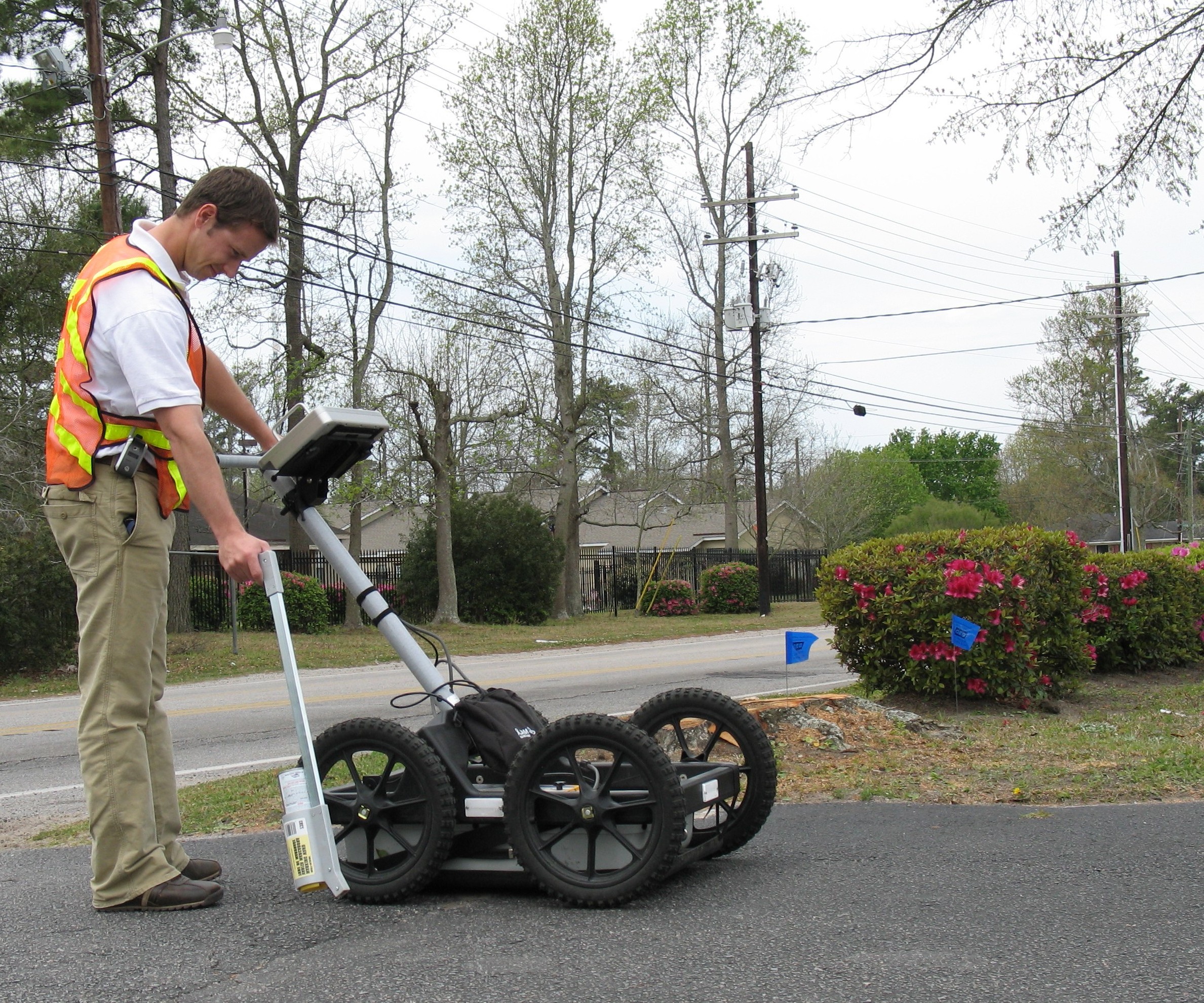
GPR locators send a signal through the soil which bounces off objects and returns a signal to the unit’s receiver providing vertical and horizontal positions with a display of the object on the unit’s screen. Tracer wire is unnecessary. Most models are on wheels attached to handlebars similar to a lawn mower, and the operator pushes the device across the ground to locate and view a representation of what’s below.
However, GPR also has limits, the most important being that its performance is much less effective in dense soils.
Representatives of key suppliers of GPR locators and one firm that offers geophysical services that include the use of proprietary GPR locating equipment, discussed information about GPR locating technology with Underground Construction.
Mala USA, Vincent Ferrara, Senior Account Manager: The primary advantage of GPR is that it detects not only metal pipes but all types of material. A tracer wire is not needed to direct connect to any utility. Sometimes GPR is the only solution for finding nonmetallic utilities without a tracer wire in dry, sandy soil. By pushing the GPR system across the surface of the soil, the unit provides a readout of the subsurface. On the GPR screen, the operator sees a hyperbolic indication of the buried utility with accurate horizontal and vertical positioning. The closest and simplest analogy is an image similar to that of a fish finder.
The latest GPR systems for utility locating are more compact, easier to use and affordable than anything previously produced.
The main limitation of a GPR locator is that it is highly dependent on soil conditions to work its peak performance. In more conductive soil conditions, the radar waves will not return to the receiver and there will not be a clear data set.
GPR manufacturers are constantly upgrading the performance of their antennas and software. Unfortunately, I do not see any solution to the GPR soil condition problem in the near future. But with adjustments and changes in filters and data collection methods, a skilled GPR technician can extract some information out of even a poor soil condition. (Mala USA manufactures X3M and Easy Locator GPR equipment for locating underground utilities.)
Sensors & Software, Greg Johnston, applications geophysicist: Conceptually, good analogies for GPR are fish finders or ultrasound medical imaging (although they both use sound waves rather than radio waves). A GPR locator uses a transmitter to send radio frequency electromagnetic waves into the subsurface and a receiver to collect the signals that reflect back to the surface from objects or materials with contrasting electrical properties. Data is typically recorded at multiple positions along a survey line on the surface.
The big advantage of GPR for the construction industry is the ability to detect nonmetallic objects like plastic and concrete pipes. GPR is nondestructive, easily deployed and provides fast, real time, interpretable images of the subsurface. Further, since GPR provides a complete image of the subsurface, it can also detect unanticipated objects like old foundations or changes in the soil or rock structures that might impact construction plans.
GPR is most effective in materials with low electrical conductivity, generally but not always coarse grained soils like sands and gravels, hard rock (granite, marble, basalt, limestone, salt), concrete, asphalt, fresh water, snow, and ice.
The biggest limitation, by far, is that GPR penetration into the subsurface is limited in materials with high electrical conductivity. For example, clay soils can reduce penetration down to just a few feet. Another limitation is data acquisition time. Collecting individual survey lines is very fast but detailed grid collection over large areas with a single GPR system can take many hours to days. This means that large grids with tight line spacing, the type of data set that greatly assists in the interpretation and understanding of the subsurface are rarely done, except by academics who have the time.
GPR data typically is presented as a real time 2D cross sectional image of the subsurface. If multiple cross sections are collected in a grid pattern, the data can be processed and presented as 2D depth slice maps or 3D volumes that can be rotated, sliced and peered into by selectively removing weaker signals to reveal targets associated with stronger signal reflections. Depth slice and 3D images are becoming more widely used because they are generally easier for most people to understand.
GPR provides a “pseudo image” of the subsurface that indicates the position and depth of electrical changes in the subsurface. These changes can be from objects located in the subsurface (i.e. pipes, cables, rebar, rocks, tree roots, foundations) and also changes in the rock or soil structure itself (i.e. soil stratigraphy, fractures, disturbed soil, cavities or sinkholes). It is important to understand that since radio waves have much longer wavelength than visible light waves, GPR images have much less resolution than our eyes see or what a photographic image would provide.
Current GPR systems like the Noggin SmartCart have been made so simple to use that anyone can be quickly trained to use them effectively. Simple GPS integration has made it easy to take GPR data into GIS software and quickly display processed results on Google Earth.
It will be difficult to overcome mother nature on GPR penetration into electrically conductive soils because the transmitter powers required to do so are not practical or legal under the radio frequency emission regulations of most countries. However, the use of GPR will grow from the increased productivity offered by multichannel systems. These systems, coupled with advanced positioning systems, even inside buildings, will soon make real time 2D map and 3D images a reality. (For utility locating, Sensors & Software offers Noggin SmartCart GPR systems and pulseEKKO PRO equipment with a full range of antenna frequencies.)
Vermeer, Keith J. Sjostrom, senior project engineer: GPR systems such as our four wheel cart deployment model are best suited as a utility detection tool within a designated area (intersection, street, construction site, etc) or along a specific bore path or proposed bore or excavation path. Detected targets can be located in real-time quickly and easily and before any excavation commences. Because of the shielded antenna, it can work in areas having EM interference such as overhead power lines, metal buildings and fences, and vehicles. GPR also can be effective in locating multiple targets within congested areas.
Generally speaking, GPR systems perform much better in drier soils and sandy soils. But other factors also determine how effective a GPR system will perform including: size and diameter of the target, composition of the target, depth of burial of the target, and expectations and experience of the GPR operator. GPR systems perform less effectively in soils that are comprised of clay material, have high percentages of mineralization, or high moisture contents.
GPR locating systems offer several advantages, including the ability to detect metallic and nonmetallic targets, and generate a continuous data profile view along the survey path presented in real time during data collection. Also, target location can be determined very accurately, depth information can be readily determined provided that the GPR system is properly calibrated, and today’s GPR systems have easy to use operator interfaces.
The reduced ability of a GPR system to detect buried targets in clayey or conductive soils is the primary system limitation. Other perceived limitations include higher costs compared to standard locators and that high quality GPR interpretation generally requires an experienced operator. In addition, most people introduced to GPR have been either oversold about a system’s capabilities or have unrealistic expectations of what a GPR system can do.
Basic GPR technology is much the same as was used 10 to 15 years ago. However, improvements such as cart based GPR systems, user friendly software, and lower system costs have more readily placed the technology in the hands of technicians and engineers for use on everyday projects.
The next big advancements in GPR utility locating likely will be in the areas of stepped frequency or swept frequency radar systems. Unlike pulse systems which send out discrete signals centered around a particular frequency, stepped or swept frequency systems provide a broad range of distinct frequencies in order to maximize information returned from a buried target for size, depth, and composition. (Vermeer markets the Interragator EZ GPR single channel, pulsed radar system.)
Ditch Witch, Mike Dvorak, electronics account manager: A GPR locator works like any other radar – it sends out an electronic signal that bounces off “something” and returns to the home base. In the case of the GPR location equipment, the unit and signals are tuned for use in the soil. The information is presented to the operator on a lap top computer. The sign of a pipe or some other object underground is a “hyperbola” that shows up on the unit’s screen.
A GPR locator can locate both metallic and nonmetallic objects. Soil conditions do limit the ability of a GPR. Moisture, clay and sand content are some of the primary factors that limit the depth a GPR can “see.” GPR equipment works best in sandy loam soil conditions and in areas where soil conditions are consistent. It also works well on concrete and asphalt. The skill of the operator can either reduce or enhance the successful use of a GPR.
GPR technology continues to improve to make locators more effective in more soil conditions. Plus, the images presented are clear and easier to read. And the price continues to come down. (Ditch Witch markets the Model 2150GR, a dual frequency GPR locator.)
Underground Imaging Technologies (UIT), Mark R. Wallbom, chief executive officer (UIT provides geophysical services with proprietary equipment, including the TerraVision II GPR locating system). GPR is not a silver bullet for all challenges but it is one tool in the box of tools that should be employed as required. Given optimal soil conditions and non congested areas that are relatively flat, GPR surveys can be very effective and dramatically reduce field instances and safety concerns. When a correctly configured GPR unit is applied to a specific task, and the environment in which the GPR unit is used is conducive to achieving good results, the advantages of using GPR are enormous.
However, GPR’s ability to locate buried pipe and cable is limited by soil conditions, and it has been estimated that about 50 percent of the U.S. is not suitable for achieving good results using GPR.
A multi array GPR provides much more information than is possible with a single channel/antenna system, and our multi array GPR unit employs 14 separate antennas. Comparative tests have reported that a multi antenna system achieved a probability of detection higher than 90 percent, rather than the 60 percent or less typical of traditional single antenna GPR systems.
Recent improvements in speed of electronic components has led, and is leading, to improvements in both the speed and quality of GPR data acquisition. A better understanding of effect of antenna polarization and the use of multiple antennas has led to better data quality in terms of how the earth is sampled to detect and image targets. Nearly all GPR systems in the world are pulsed transmitter systems but stepped frequency continuous wave systems are being tested and may lead to improved results at least under certain conditions.
FOR MORE INFORMATION:
Mala USA, (843) 852-5021, www.malags.com
Sensors & Software, (800) 267-6030, www.sensoft.ca
Vermeer Corp., (888) 837-6337, www.vermeer.com
Ditch Witch, (800) 654-6481, www.ditchwitch.com
Underground Imaging Technologies, (518) 783-9848, www.uit-systems.com

Comments