
June 2009 Vol. 64 No. 6
Features
Organic “High-Build” Spray-in-Place Liners – An Emerging Class of Rehabilitation Methods
As the water distribution infrastructure continues to deteriorate across North America, there is a continued need to develop pipeline rehabilitation methods that are cost effective and minimally disruptive, while also minimizing the time a pipe must be taken out of service.
Spray-on linings that satisfy the requirements of NSF 61 are one such emerging class of rehabilitation methods for pipes and conduits subjected to internal pressure. This article provides an overview of spray-on lining methods in general, and chemically hardened lining products in particular. The article focuses on polyurethane and polyurea, which are gaining growing acceptance in various segments of the municipal water facilities rehabilitation market in Europe and North America.
Background
Spray-on linings currently used in waterline rehabilitation are either cement-based or polymer-based as seen in Figure 1. Each of these spray-on linings is formed by two or more substances that, when combined, result in a chemical reaction that form a hardened material shaped to mold along the pipe wall or pipe deformities. The application of lining for the rehabilitation of water pipes is century-old, with hand-applied cement-mortar lining dating back to the early 1900s. Spray-application of cement-mortar lining in larger diameter pipes started in the 1930s, and was expanded to small-diameter pipes in the late 1950s. Cement-mortar lining provides a corrosion resistant barrier between the inner wall of the pipe and its contents, increases flow and improves water quality by addressing color and odor issues. Its cost-effectiveness and ease of application made cement-mortar lining a popular means for rehabilitation of water pipes over the past 50 years.

However, hardened cement mortar does not possess significant tensile strength and therefore cannot provide the host pipe with additional internal pressure capability or compensate for lost internal pressure capacity in the case of substantial wall thickness loss, limiting its application to cases where the host pipe has maintained its overall structural integrity (Bontus et al., 2005). In an attempt to increase its tensile strength, steel fibers were added to the cement-mortar mixture with some success. Another shortcoming is the relatively long setting time and the relatively slow strength gain rate, which necessitate removal of the waterline from service for a prolonged period, requiring the installation of a temporary water supply system.
The term “polymer” represents a broad class of materials that, by definition, are large covalently bonded chains formed by the combination of smaller molecules. Polymers used for waterline rehabilitation are classified as synthetic “engineered lining/adhesive.” These polymers combine a resin and a hardening agent to form a fast curing thermoset material with a crosslinked molecular composition. Depending on the type of adhesive formed, the reaction may require a curing aid such as a catalyst additive or heat.
The resin and curing agent for the three polymers discussed are typically in a liquid state prior to and when combined. Once the chemical reaction is complete, 100 percent of the resin is transferred to a solid state; hence the term, “100 percent solids.” Depending on the type and hardening agent combined with the resin, the resultant polymer may possess either rigid or elastic material properties (also called elastomeric). Polymer linings are either nonstructural (AWWA Class I) or semi-structural (AWWA Class II or III), where a differentiation is made between liners with inherent ring stiffness versus those that rely entirely on adhesion to the host pipe to be self-supporting. Semi-structural liners can be applied to the pipe wall in multiple layers called “high build,” and depending on their design and application, may be a Class II or Class III.
Developed 40 years ago, fusion-bond-epoxies were adopted by many water utilities during the 1990s, and are now well accepted and widely practiced for water quality enhancement and corrosion protection for steel, ductile iron and cast-iron pipes. Epoxies are formed by a reaction between bisphenol A (the resin) and epichlorohydrin (the hardener). These chemicals are typically combined with a catalyst (dicyandiamide, aliphatic diamines or aromatic amines) at an elevated temperature to initiate the reaction.
The setting characteristics of epoxy resin necessitate minimally a 16-hour cure period before commencement of return to service procedures, resulting in a 36-hour shutdown period during which customers must be served by temporary supply arrangements. The application of multiple coats further increase construction duration and cost, thus epoxies are typically applied as a thin layer aimed at corrosion protection, the bridging of small crack and gaps and for improving the pipe’s hydraulics (Guan 1999). For this reason, epoxies are considered to be “non-structural,” and are expected to add little to the structural strength of the host pipe. However, several vendors are currently working on high-build epoxy formulations.
Polyurethane and polyurea lining materials are often placed in the same chemical category. Both polyurethane and polyurea linings are produced using an isocyanate compound, but each uses a different reacting resin producing a unique molecular chain. Polyurethane linings use a Hydroxl (OH)-ending blend called a polyol as the hardened resin, while Polyurea uses an amine (H2N)-ending blend. The polyurethane reaction utilizes a catalyst similar to that of epoxies to produce the resultant material. This reaction produces a 100 percent solids material within a matter of minutes, so additional layers for high build can be easily applied.
The polyurethane is applied centrifugally onto the pipe surface in a thickness typically between 120 and 200 mils (3 and 5 mm) using an air-driven spray head that is advanced through the pipe to form the lining. Commercially available products include the Copon Hycote 169 (the US version is named Scotchkote 169) and Spraywall. Polyurethane is also used for coating of manhole structures for the purpose of corrosion resistance (typically utilizing two layers of 75 mils each, for a total thickness of 150 mils). These coatings exhibit high chemical resistance, but are moisture sensitive and the surface of the host structure must be completely dry to ensure adhesion to the substrate.
In polyurea materials, the reaction with the amines produce very short gel times and the substance hardens very quickly (several seconds to minutes), producing a 100 percent solids material.
The installation of polyurea requires the use of a plural component, high pressure and high temperature application system (Primeaux, 2004). A catalyst is not necessary using this application technique. Polyurea is suitable for high temperature applications, as it features high heat resistance properties. Polyurethane linings can be produced with different types of polyols that can provide a rubber-like property used in pipes that may have flex potential. The urea group chain tends to produce elastomeric materials, so if a more rigid material is needed for additional structural stability and flex is not a prime concern, polyurethane linings can be used.
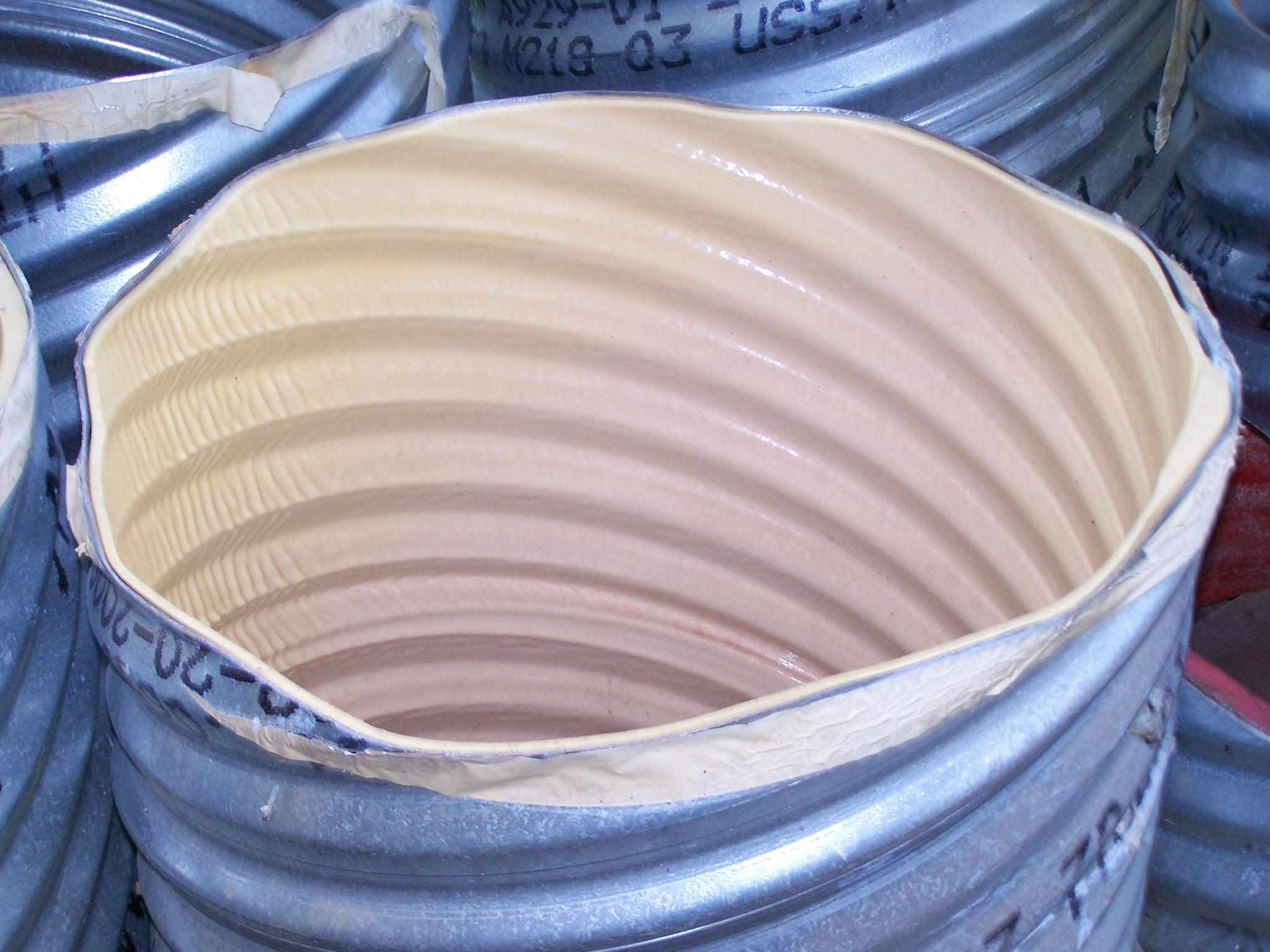
The Polyurea is applied onto the pipe surface using a robotic application system or by conventional hand-applied procedures in multiple thin layers to build a pipe inside a pipeline with wall thickness between 20 and 1000 mils (0.5 and 25 mm) or greater (Figure 2). Examples of the technology are the PolySpray Structural Liner. Polyurea coating typically utilizes two layers of approximately 90 mils (180 mils total thickness). Flow can be reinstated in as little as 60 minutes, allowing same day return to service. An example of a polyurea coating is PCSI Polyurea Manhole Coating.
[inline:coated.PNG]
[inline:coated2.PNG]
Fig 2. Twenty-four inch corrugated metal pipes coated with different formulations of polyurea awaiting testing at the Trenchless Technology Center
Polyurea and 100 percent solid polyurethane form a new class of organic “high-build” coating systems. These products, which are able to be built to substantial thicknesses within minutes, feature a very quick curing time that supports same day return to service and exhibit pressure ratings adequate for most municipal water mains, making them attractive rehabilitation methods for municipalities looking for short downtime for potable waterlines and force mains (Johnson et al., 2002). However, for this potential to materialize, appropriate qualification and service testing for pressure pipe applications needs to be performed, long-term performance characteristics established and design procedures developed. Procedures for operation maintenance, installation of new services and emergency repairs of rehabilitated pipe sections are also concerns that must be addressed before these technologies can come to fruition.
The following sections describe the results of testing 28 panels of 100 percent solid polyurethane and polyurea under varying thickness subjected to a uniformly incremented water pressure until failure (burst-test). These tests are part of a comprehensive research initiative undertaken by the Trenchless Technology Center which is aiming at the development of an extensive database, and subsequently a predictive model, for organic “high-build” spray-in-place liners. It is anticipated that this research effort will support the establishment of a design procedure for these products.
Mechanical properties
A series of tests of both polyurethand and polyurea linings were performed in accordance with ASTM D638 to determine the stress versus strain relationship of the materials used in the construction of the test panels. Coupon samples were cut from each panel in both, lateral and longitudinal directions. The samples were then tested to evaluate their tensile modulus and limiting tensile strain as per ASTM 638. For the 15 samples of polyurea, the elastic modulus was found to range between 150,000 psi and 230,000 psi, with an average value of 189,000 psi. Strain at failure was found to be 0.049. The average tensile modulus for the polyurethane was determined to be 425,000 psi, and the strain at failure 0.02. Graphical representations of the experimentally measured stress-strain curves for the polyurea and polyurethane formulations tested are shown in Figures 3 and 4, respectively.


Fig 4. Stress-strain curve for polyurethane (as per ASTM 638)
Apparatus, experimental set-up (subhed)
The testing frame consists of two main components; the pressure side and the opening side. The pressure side of the frame was designed to apply a uniform pressure to one side of the panel (Figure 5). The opening side of the frame contains a circular opening, which simulates a deficiency in the host pipe wall. This opening is the region of the panel where failure occurs. Both portions of the frame contained a rigid formation of rectangular steel tubes attached to a machined flat steel plate (Figure 6). On the pressure side, the steel plate has a welded steel extension collar that creates a 24 x 24 x 1 inch cavity where the water pressure can be developed. The collar has a square groove machined inside of the bolt pattern to fit a rubber seal (Figure 5). The seal assists in maintaining the pressure inside the cavity by eliminating any minor deformities in the panel.
[inline:coated5.PNG]
[inline:coated6.PNG]
Fig. 5: Pressure half of frame with the seal installed
The opening side of the frame consists of either a 3-inch or 4.5-inch diameter opening in the center of a rigid steel plate. This opening simulates a portion of material either heavily corroded or missing altogether from the host pipe wall. The two halves of the frame are connected using 26 threaded one inch diameter rods.
A pressure supply system was designed to provide up to 1500 psi of water pressure to the frame. The system consists of a high pressure nitrogen tank supplying pressure to an interface chamber which in turn pressurizes the water within the cavity on the pressure side of the frame. A series of regulators, gauges and relief valves were installed for safety and pressure regulation. To measure the deformation of the exposed panel at the opening as pressure increases, a pivot system was designed to transfer the movement of the panel to a linear variable displacement transducer (LVDT) (Figure 7). This system protects the LVDT from damage when panel failure occurs. During testing, data from both the LVDT and the pressure transducer was collected using an Agilent data acquisition unit.
[inline:coated7.PNG]
Fig. 6: Assembled testing frame with panel.
[inline:coated8.PNG]
Fig 7. LVDT installed at panel opening
Sample Preparation
Specimens tested consisted of 31-inch square panels of the polyurethane and polyurea materials. Flat plates were used to simplify the testing apparatus. Also, the majority of current applications in the USA involve the lining of large diameter pipes that permit person entry for manual spray application of the material. The vendors provided a total of 28 of panels with thicknesses ranging from 0.14 inch to 0.42 inch. To accommodate the 26 threaded rods required to assemble the testing frame, 1⅛-inch holes were drilled into the panel along the edge using a steel frame template (Figure 8).
[inline:coated9.PNG]
Fig 8. Test panels of poluyrea (left) and polyurethane (right)
Testing procedure
Once the panels were prepared and installed in the test frame, the transducers were mounted and the data acquisition system was powered to begin acquiring data. The pressure cavity was then filled with water to evacuate the air. Once the cavity was filled, the pressure system was transferred to the nitrogen side of the interface chamber to begin applying pressure to the water behind the panel. The pressure was applied in 50 psi increments with approximately 60 seconds between increments, allowing the pressure to stabilize and form a uniform distribution of the load across the panel. These increments of pressure were applied until failure occurred.
Mode of failure
Polyurethane Panels
In each of the 23 panels tested failure occurred in a concentric fashion with respect to the opening walls. Fragments from the panel were collected and pieced together to their original configuration. Visual inspection of the fragments indicated that the material assumed little or no permanent deformation throughout the test (Figure 9). The outer edge of the puncture holes and the fragments of the material have an angular shape. This shape is indicative of a classical punching shear failure, where the failure plane occurs at approximately 45 degree inclination angle to the surface of the panel. Furthermore, the fragments fit together with no sign of permanent deformation suggesting that little, if any, bending occurred prior to failure.
[inline:coated10.PNG]
[inline:coated11.PNG]
Fig 9. Puncture hole and fragments – polyurethane
Polyurea Panels
In each of the five tests, the material failed in a concentric fashion with respect to the opening in the test frame. For the thinnest panel, the punctured fragment of panel remained in one piece. Visual inspection of the fragments indicated that the material assumed some permanent deformation as the test progressed (Fig. 10). There was also evidence of bending, as the shape of the fragments appeared bent toward the center of opening. The outer edge of the puncture holes and fragments of the material are mostly smooth, which is indicative of a ‘plug’ shear failure mode.
[inline:coated12.PNG]
Fig 10. Puncture hole and fragments – polyurea
Relationship between failure pressure and panel thickness
Figure 11 provides a visual display of the failure pressure and panel thickness relationship for the polyurethane specimens. The data suggest that the failure pressure is directly related to the thickness of the material. Also, as the opening size was enlarged, failure pressures decreased for panels with the same thicknesses, as would be expected considering the increase in unsupported panel surface area.
A linear regression model was used to develop the following predictive equation that considered the failure pressure, opening size and the thickness of the liner:
Pf = 344.5 – [171 * D] + [(2500 * t] (Eq. 1)
Where Pf is the short-term burst pressure (psi), D is the diameter on the opening (inches) and the t is the thickness of the panel (inches). Equation [1] yields a relatively accurate, yet conservative value of the short-term burst pressure for a given combination of polyurethane liner thickness and opening (‘defect’) size. The equation is applicable only for liners with similar material properties to the material tested for this study. Equation 1 does not consider parameters that could control long-term strength of thermosetting materials, such as creep and fatigue.
In the case of the polyurea, Figure 12 provides a visual display of the failure pressure and thickness relationship for the five panels tested. The preliminary trend line generated from the results indicates a linear relationship between failure pressure and panel thickness (R2 = 0.842). To date only tests utilizing a 3” opening have been performed. Based on the preliminary results the following linear mathematical expression was derived:
Pf = 1069 (t) – 1.731 (Eq. 2)
Where Pf is the short-term burst pressure (psi) and the t is the thickness of the panel (inches). It is expected that testing of additional panels at varying thicknesses will provide an even higher level of confidence in this relationship. As additional formulations are tested, TTC researchers intend to incorporate the material properties as another variable in the regression model, allowing a further generalization of the prediction equation to cover a wide range of formulations.


Fig 12: Burst pressure vs. thickness for polyurea panels
Case Studies
Case Study 1: Rehabilitation of a water intake at Springerville Generating Station
Springerville, a town of 2,000 located in the eastern mountains of Arizona, is home to Tucson Electric Power’s (TEP) 1160 megawatt Springerville generating station, a modern, pollution-controlled coal-fired electric power plant that services private and public customers from southern Colorado to San Diego, California.
In March 2009, TEP undertook the relining of the water pipe intake of Unit 1 (a 380 megawatt generating system). The project consisted of relining 1,800 feet of 96-inch and 620 feet of 72-inch steel pipe. TEPs representatives contacted Innovative Painting & Waterproofing, an Arizona-licensed contractor based in Brea CA, for replacing the existing mortar lining with 60 mils (1.5 mm) of polyurea coating. Innovative was retained to apply the polyurea lining using a combination of robotic plural-component spray equipment (designed and developed in-house in cooperation with the Trenchless Technology Center; see Figure 13) and hand-spray methods in areas inaccessible to the robotic systems.
The Graco/Gusmer material pumps used for the project utilized the latest data recorder and flow meter tracking hardware and software, providing real-time and historical pressure, temperature, flow and other critical data. Hartman Walsh Corporation was retained to handle the demolition of the existing mortar lining and perform hydro/abrasive blasting of the pipe’s interior surfaces. The entire project was set for completion within a tight 4-week window during a pre-scheduled 5-week shutdown of Unit 1.
To complete the project within the allotted time required Innovative to operate around the clock for part of the project duration. The project was completed on time and budget.
[inline:coated15.PNG]
Fig 13. A robotic unit used to apply a 60 mil polyurea coating to nearly half a mile of 96” and 72” steel pipe.
Rehabilitation of a 60-inch CMP culvert
In early 2007, the City of Norristown, Pennsylvania discovered that a 60-inch diameter CMP storm sewer had developed severe structural problems due to corrosion and abrasion wear. The conduit served as a drainage pipe beneath a heavily traveled highway. Excavation and replacement of the damaged pipe would have caused numerous delays and detours for traffic in the area. A Sprayroq Certified Partner was contacted to explore the possible applicability of a structural repair utilizing the Spraywall technology. The first step was to prepare the internal surface of the pipe for the application. The invert (bottom channel) had suffered severe corrosion and abrasion. To prepare this part of the conduit, a 24-inch wide concrete swath was poured along the entire 600 foot length of the pipe to rebuild the invert and make it suitable for the application of Spraywall. The conditions that the culvert was exposed to (i.e., depth of cover, hydrostatic load and any live loads) were reviewed as to provide for the proper thickness of the applied Spraywall. It was determined that 250 mils (6.5 mm) thick polyurethane liner was needed to rehabilitate the conduit. After the concrete swath cured in the invert, the pipe was power washed using a high pressurized water jet cleaner to remove debris and corroded material on the surface of the culvert. After drying, the CMP was sprayed with the Spraywall material until the desired thickness was achieved. The application of the Spraywall material took two days to complete (Figure 14).
[inline:coated16.PNG]
Fig 14. Application of a 250 mil of polyurethane coating for the rehabilitation of a 60” CMP culvert.
Summary
Organic ‘high-built’ spray-in-place polymers are coming to age as a viable rehabilitation method for gravity driven, and more recently, pressure pipes. A new generation of rapid setting semi-structural polymeric lining products, such as the Copon Hycote 169HB, which is expected to enter the market place over the next few years, offer mechanical properties that allow it to serve and an alternative to polyethylene-based rehabilitation technologies. The combination of robotic-spray and hand-spray equipment allow spray-in-place polymer to be applied to pipes and conduits as small as 4-inch or as large as 120-inch in diameter, as well as a wide range of cross-sectional geometries. In striving for wider acceptance, spray-in-place polymers were required to undergo appropriate qualification and service testing for pressure pipe applications. Long-term performance characteristics need to be further established and consensus-based design procedures need to be developed. Furthermore, procedures for maintenance, installation of new services, and emergency repairs of rehabilitated pipe sections need to be addressed before these technologies can come to fruition. While facing a number of challenges, ‘high-built’ spray-in-place polymers are expected provide decision-makers with a new set of tools for getting their projects done quicker, with less disruption and economically.
Acknowledgement
The authors would like to acknowledge the financial support provided by SprayRoq Inc. of Birmingham, AL, and Innovative Painting and Waterproofing Inc. of Brea, CA. The contribution provided by Dr. Ray Sterling, director of the TTC, and technical support provided by Nathan Pettit, a technician specialist at the TTC, are also acknowledged.
About the authors: Erez N. Allouche, PhD, P. Eng. is the associate director and associate professor of Civil Engineering for the Trenchless Technology Center at Louisiana Tech University (allouche@latech.edu ). Eric J. Steward is a research associate for the TTC at Louisiana Tech (ejs018@latech.edu).
REFERENCES
Bontus, G., M. Brand, K. Oxnar, and J. Gumbel. “Trenchless Rehabilitation Options for Potable Water Systems – the Wave of the Future.” Bridging the Gaps, Technological Development to Practical Application. Saskatoon, Saskatchewan: 57th Annual Conference of the Western Canada Water and Wastewater Association, 2005.
Guan, Dr. Shiwei. Common Questions on 100% Solids Polyurethane Lining. April 1999. http://www.geocities.com/pulining/pwsp.htm (accessed November 24, 2008).
Johnson, D.H., E. Levin, and J. Birdsall, 2002. “New Process for Structural Rehabilitation of Pressure Pipelines,” Proceedings of the No-Dig International Conference, Montreal, Canada, April, 10 p.
Primeaux, Dudley J. “Polyurea vs Polyurethane & Polyurethane/Polyurea: What’s the Difference?” Polyurea Linings: That Was Then, This Is Now, 2004 PDA Annual Conference. Tampa: Primeaux Associates, LLC, 2004. 1-20.
TTC Industry Advisory Board
Manufacturer
Ben R. Bogner, AOC, LLC
Robert Cannon, Composites One
Joe Purtell, CUES, Inc
Rick Turkopp, Hobas Pipe USA, Inc.
Lynn Osborn, Insituform Technologies, Inc.
Larry Kiest, Jr, LMK Enterprises, Inc.
Michael Burkhard, Reline America, Inc
Denise McClanahan, Reynolds Inliner, LLC
L. Grant Whittle, Ultraliner, Inc.
Tom Marti, Underground Solutions, Inc.
Associations
Dennis Jarnecke, Gas Technology Institute (GTI)
Patrick Mann, GCTA
Vic Weston, LA Contractors’ Educ. Trust Fund
Irvin Gemora, NASSCO
Media
Bernie Krzys, Benjamin Media
Robert Carpenter, Underground Construction
Consulting
Andy Dettmer, Carollo Engineers, P.C.
Richard Nelson, CH2M HILL
Brian C. Dorwart, Haley & Aldrich, Inc.
Joseph W. Barsoom, J. Barsoom Consulting Services
Glenn M. Boyce, Jacobs Associates
Robert Morrison, Jason Consultants
Mac Bakri, KBR – Kellogg Brown & Root, Inc
Joseph W. Barsoom, Parson Brinckerhoff
James H. Forbes, Jr., Pipeline Analysis, LLC
Norman E. Kampbell, Rehabilitation Resource Solutions, LLC
John J. Struzziery, S E A Consultants Inc.
Contractor
David Ellett, BRH-Garver Construction, LP
Cliff Tubbs, Laughlin Thyssen, Inc.
Public Works
Irene McSweeney, Boston Water & Sewer Commission
Wayne Querry, City and County of Denver
John Griffin, City of Atlanta
James Gross, City of Columbus
Michael Hines, City of Dallas
Joe L. Smith, City of Houston
John Morgan, City of Indianapolis
Keith Hanks, City of Los Angeles
Sean Benton, City of Monroe, LA
Dino Ng, City of New York – DDC
Richard Aillet, City of Ruston
Ali Mustapha, City of Shreveport
Comments