
July 2010 Vol. 65 No. 7
Features
Rehab Of A 100-Year Old Brick Storm Sewer
In what should have been a relatively simple project with a few significant yet manageable challenges, circumstances quickly changed to create the “job from hell.”
This sewer rehabilitation project is located in the southwest sector of Washington, DC. What was at one time the USEPA building was demolished and the site is being developed for mixed use. The Waterfront Mall Project will contain retail stores, restaurants, offices and residential units. Through the middle of the site there is an existing 100-year-old, 90-inch diameter storm sewer about 800 feet long. About half of the length of pipe is all brick, consisting of three layers. The other half of the pipe consists of a bottom portion constructed of brick (below the spring line) and the upper half is unreinforced concrete. The pipe makes one 90 degree short radius bend about mid length.
The sewer is now a storm drain but previously it was a combined sewer. It empties into the Potomac River about 1,000 feet downstream of the project site. The sewer is owned and maintained by the District of Columbia Water and Sewer Authority (DCWASA). The new development included the proposed construction of a building and a parking garage over the existing sewer. Although the sewer was in relatively good condition, especially after 100 years of service, DCWASA requested that the sewer be rehabilitated by the developer. This was primarily due to the fact that access to the pipe would be severely limited after the buildings were constructed which would diminish the ability of the owner to maintain or repair the sewer.
It was decided to use the Danby lining system to rehabilitate the sewer. This is a grouted-in-place-liner (GIPL) which has proven experience in the U.S. for over 20 years. This lining system consists of 12-inch wide PVC panels delivered to the site in 300 foot coils. This is a man-entry system so the pipe needed to be dry. Access to the pipe interior was relatively good since there were existing manholes at the upstream and downstream limits of the rehab section. A new manhole about midway had been constructed. The installation contractor was Boyer Inc. of Houston.
Anticipated challenges
Although this was a relatively straight forward job, there were several challenges identified.
• This was a very busy construction site with numerous subcontractors and trades working on different aspects of the overall job. This was primarily a building project and rehab of the existing storm sewer was just a necessary evil required to get the project approved. Therefore the rehab contractor was viewed as the “low man on the totem pole” when it came to priority to access certain parts of the site. The lay down and work areas were greatly restricted;
• The existing storm sewer discharged to the Potomac River through a flap gate. Due to a combination of age and debris, the flap gate did not seal well. This is common and to be expected. However the tidal influence of the river resulted in two – 7 feet of standing water always being in the pipe;
• Even medium size rains could cause the pipe to fill up with storm water with only 10 – 15 minutes warning; and
• There were no plans of the existing sewer but a limited inspection determined that the sewer was in relatively good condition and the curve had a radius roughly equal to 125 feet. The curve was partially a smooth radius and partially made of chords with angle points.
The project site is at K Street & 4th Street SW a little less than a mile southwest of the capitol.
Pipe preparation
The first order of business after mobilization and site move-in in mid July 2009, was to control the tidal river backwater and the storm water flow. During the preliminary site investigation the depth of water in the sewer was measured at about two feet. However, it was soon discovered that this measurement was taken during an extremely low tide time. The actual depth of standing water in the sewer varied from two feet to as much as 7 feet. Several attempts to control this backwater were made using a large off-road construction tire tube and then a sand bag weir. The final solution was to use a fabric-type inflatable pipe plug that was flexible enough that it could be rolled up and inserted through the manhole. The edges were reinforced and the plug chained to the top of the downstream manhole. This plug also served to prevent short-circuiting of the ventilation system. Even during dry weather there was a small base flow in the storm sewer. A small sand bag weir and submersible pump was installed at the upstream manhole which was piped to discharge at the downstream manhole.


After the river backwater and pipe base flow were under control and the ventilation system established, cleaning of the sewer was accomplished. The debris in the pipe was mostly sand and silt with an occasional brick or chunk of concrete dislodged during the installation of a lateral pipe. About half the debris was removed manually using wheelbarrows. The remaining debris was removed using a jet rodder and vactor truck. In preparation for the lining, the walls of the sewer were cleaned using a high pressure water blast of 6,000 psi. This removed any dirt, oil, grease, loose mortar, concrete, aggregates, laitance or other contaminants. What remained was a clean, competent brick and concrete sewer. There were eight abandoned services and one groundwater leak that were also plugged.
Twice during the cleaning operation there were rain storms. Crews and equipment had to be quickly removed from the sewer and the downstream plug deflated. These events stopped the sewer cleaning for six days.
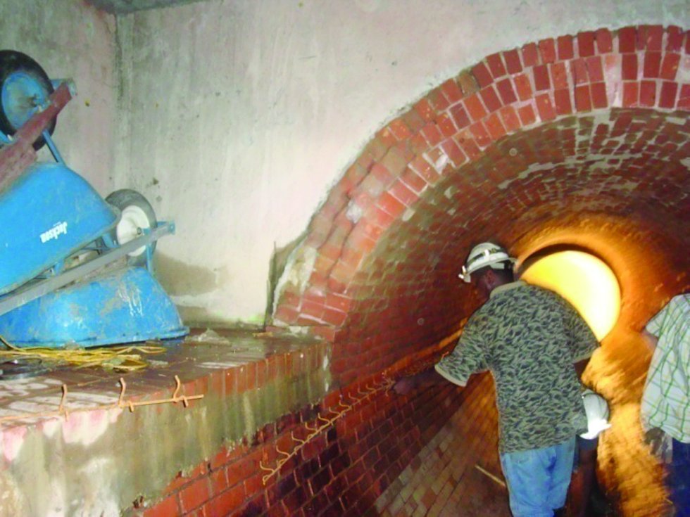
Liner installation
As can be seen in the drawings, the three inches of grout in the annular space will result in a liner ID of 84 inches. In order to maintain the three-inch minimum grout thickness, steel spacers (bolsters) were mounted on the pipe wall. The liner is fed into the pipe through the manhole, then pulled into position. The panels are spiral wound by connecting the adjacent panels with a joiner strip. The joiner strip is installed using a pneumatic palm hammer. The end of the next coil is connected to the previous one with an “H” strip splice. A steel buoyancy restraint angle is anchored at the bottom of the liner. Grout bulkheads are placed about every 400 feet using hydraulic cement.


During the liner installation, there were several times when storms necessitated evacuating the sewer and delayed the completion of the lining by almost two weeks.
Grout
The PVC liner panels, besides being water-tight and corrosion-resistant, are essentially the “form” for the high-strength grout. It is the cementitious grout that provides the structural rehabilitation of the pipe. The current state of stress of the existing pipe was determined through a finite element analysis and the minimum grout thickness was calculated using the Flexural Stress Cracking Design Method (Composite Material Design). The grout consists of Portland cement (57 percent), Fly Ash (43 percent), and water and super-plasticizer admixture. Although the design is based on a grout compressive strength of 6,000 psi, typically the tested 28-day strength is 7,000 – 9,000 psi. The grout will normally set-up in four to 5 hours (firm to the touch) and develop a compressive strength of more than 1,000 psi in 24 hours.

The cement and fly ash are premeasured and pre-mixed and delivered to the job site in 1,000 pound “super sacks.” The grout components (full sacks) are introduced into the Colloidal Mixer which uses a high shear pump and baffles to recirculate and thoroughly mix the constituents, which is done for eight to 10 minutes. The grout mix is then transferred to the agitator/holding tank. Water and then the cement/fly ash blend is added to the colloidal mixer for the next batch. The grout mix remains in the agitator/holding tank for up to 10 minutes where it is mechanically agitated to maintain the mixture in suspension. The grout is pumped through a progressive cavity pump into the pipe to the injection point. The grout is very fluid (18 – 25 second standard flow cone).

The liner is grouted in eight lifts of about12- inches each. Grout and vent holes are drilled in the liner about every 20 feet. The grout hose discharges into the grout hole and the mixture flows by gravity into the annular space between the liner panels and the host pipe. When grout starts flowing out of the vent hole, the hole is plugged and the hose is move to the next grout hole. The next grout lift is placed a minimum of 12 hours after the previous lift is completed.

That is the sequence of operations if the work is progressing according to the work plan. In anticipation of the project, Boyer located a local supplier of cement products in the DC area, which was part of a large national supply company. Boyer obtained samples of the cement and fly ash and tested these materials to ensure the materials met specifications.
From good to bad to worse
On the first day of the grouting operation, the grout flash set, which was never a problem on previous jobs. Initially, it was thought that there was some problem with the pump, but the next day rocks, pebbles and clumps of set-up cement were discovered in the mix. The mix is supposed to contain only cement and fly ash; no aggregates. A screen was installed at the transfer hose from the mixing to holding tank and started catching rocks, pebbles and cement clumps which were causing the hose to clog up.
Once this problem was solved, random batches of the grout started flash setting. On two separate occasions, five batches had to be pumped out and wasted into a wooden box because of flash setting in the holding tank in five to 10 minutes. The supplier was again informed about this problem.
While grouting the third lift of the first section, the liner buckled. It was determined that the grout in the first and second lifts had not set, even after 36 and 12 hours respectively. This allowed the liquid grout in the upper lift to migrate downward where it exerted an excessive hydrostatic force on the lower sections of liner causing buckling. Because of the inadequacy of the grout and the buckled liner, Boyer decided to remove the liner and grout installed for the first 300 feet. Testing of the defective grout showed that it did not meet required strength requirements. New liner was reinstalled for that section. Removing the liner and grout was a tedious process that entailed cutting out the liner and then removing the hardened grout in pieces using a jack hammer.
The primary issue with the cement/fly ash blend was the inconsistency of material and apparent deficiencies in the QA/QC at the supplier’s plant. After switching suppliers for the cement/fly ash blend, no further problem with grout quality were experienced.
Conclusions
This project had many challenges, both expected and unanticipated. Between the grout problems, removal and replacement of liner and grout and 18 rain days, the job took twice as long to complete than was planned. Unfortunately from the standpoint of cost, this was not a profitable job. However, the contactor, Boyer Inc. was professional and did the right thing and corrected any shortcomings at their own expense even though the problems were caused by circumstances beyond their control.
In the end, the owner got a rehabilitated 100 year old sewer whose service life has been extended for probably another 100 years. Sometimes construction projects don’t progress as originally planned. Even though this job became a major nuisance, the problems were effectively addressed and the result was a high quality finished product
FOR MORE INFORMATION:
Boyer Inc., (713) 466-5395, www.boyerinc.com
Danby LLC, (281) 413-3977, www.danbyrehab.com

Comments