
April 2012, Vol. 67 No. 4
Features
Boring Through A Crowd
Community-owned Colorado Springs Utilities (CSU) provides electric, natural gas, water and wastewater services to 645,000 residential and commercial customers in the Pikes Peak region of Colorado.
The multi-utility approach has served the area since 1924, giving customers a single source for basic services, streamlining management and operations for construction and maintenance of infrastructure, and eliminating the potential for conflicts among separate utility providers.
When CSU recently needed to upgrade the power feed to an Agilent Technologies facility, horizontal directional drilling (HDD) was selected as the method of construction for one key segment of the installation, primarily because of the large number of existing below-ground utilities in proximity to the planned route of the pipe installation, said Mason Parsaye, general manager, Energy Services Division of CSU.

Using HDD to avoid cutting the street also saved Agilent the cost of degradation fees. The bore extended from Agilent’s property, down a 15-foot incline, leveling to cross under the high-traffic, six-lane Garden of the Gods Road.
The installation was made by one of four CSU crews headed by Bill Doyle, the CSU bore crew operations supervisor. The crews make HDD installations for CSU’s electric, gas and water operations.
Doyle said that avoiding damage to the multiple existing utilities — in addition to the routine aspects of any directional installation — made installing this section of pipe especially challenging.
Obviously careful planning was essential.
Delicate procedure
In addition to safely crossing existing utilities, it was important that tension applied to the pipe during its pullback through the pilot hole did not compromise the integrity of the pipe.
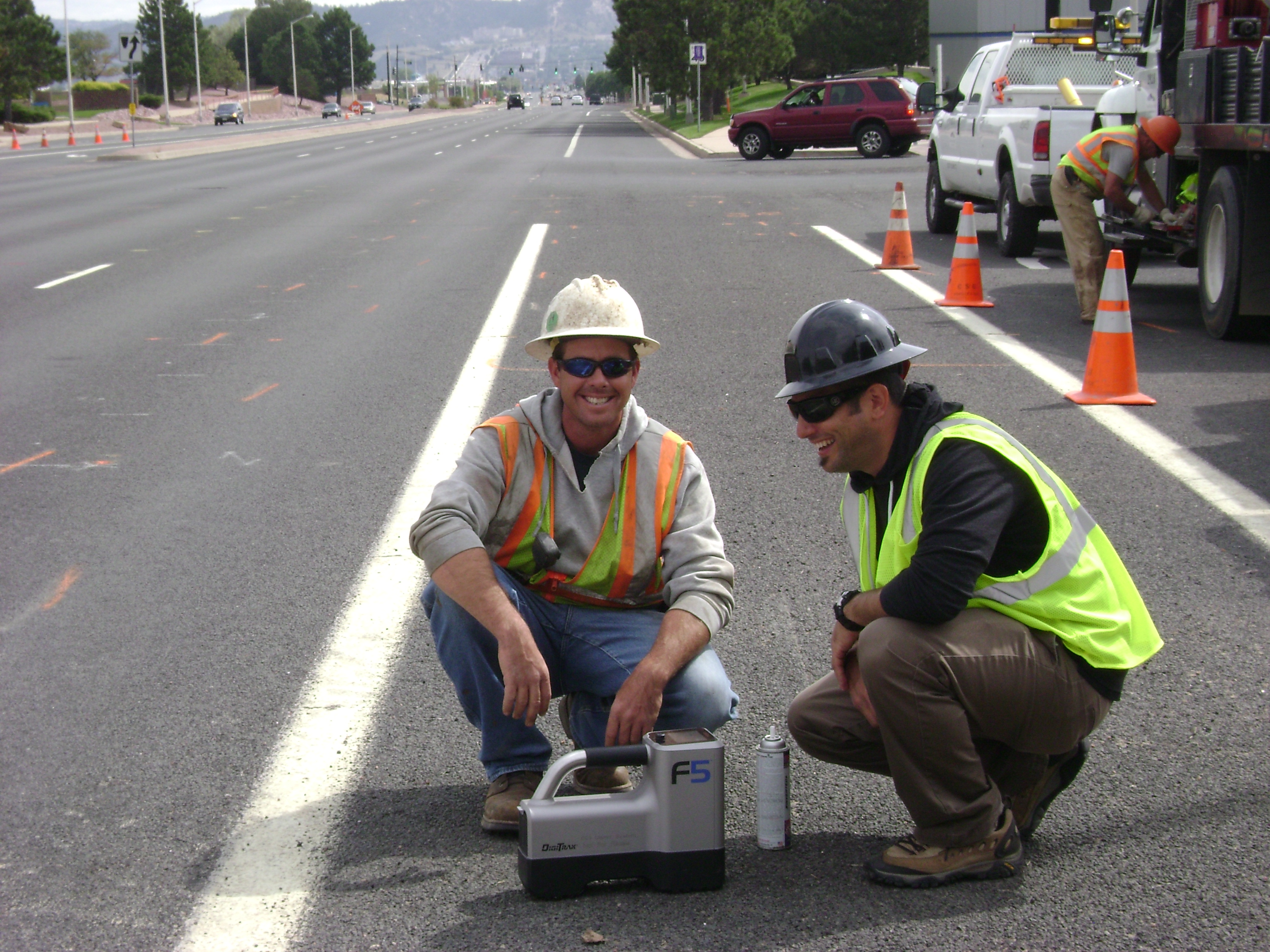
To monitor tension to the pipe during installation, the decision was made to use a TensiTrak monitoring system which required a DigiTrak F5 tracking system, said Doyle. LWD (log while drilling) software, used with the F5 tracker, provided an accurate as built of the installation.
Potholing to visibly verify and mark the locations of the existing utilities required two days, primarily because most of the utilities were in the middle of the street, said Josh Hardcastle, crew supervisor for the project. A McLaughlin V1200 vacuum excavation unit was used.
On the third day, drilling the pilot bore required only a few hours with backreaming started immediately after its completion. Backreaming continued on the fourth day, and product pullback and clean-up were wrapped up on day five, completing the HDD segment.
A Vermeer D36x50 was used to drill the 250-foot-long pilot bore and pullback a bundle of two 6-inch and one 4-inch HDPE conduits. This model drill unit is powered by a 140-horsepower diesel engine. It is rated at 38,000 pounds of pullback, 5,000 foot pounds of rotary torque and maximum spindle speed of 227 rpm. The drilling fluid pump is rated at 70 gpm. Depth of the bore ranged from 48 to 140 inches through a subsurface soil mix of clay and decomposed granite. The vacuum excavator was kept on site to remove excess drilling fluid.
“On the south side of the road,” said Hardcastle, “we had to be four feet deep so linemen could tie into a new vault. On the north side of the building — the launch point of the bore — we needed to be at a depth of four feet before dropping off the 15-foot downgrade. Among the utilities crossed were a 36-inch storm drain on the hill, a 12-inch water main, an 8-inch high-pressure gas line which we had to stay at least five feet away from, 34.5 kW and 115 kW power lines, a 6-inch low pressure gas line, a sewer line, two fiber optic cables and power feeder to a street light.”
A McElroy TracStar 412 fusion machine was used to assemble strings of pipe for pullback. Pipe sections were laid out and fused on a side street.
Separate passes were made to enlarge the pilot hole from 6 to 10 inches, then to 16 inches, and finally to 18 inches to ensure a good path for the 12-inch HDPE pipe bundle.
“Learning to use the new F5 locator on a challenging project was interesting,” said Hardcastle. “Because of the extreme change of grade from the launch point going down the hill, we had to recover at a point enabling crossing all utilities and to complete the job. With the locator and TensiTrak, we were able to record the bore path and provide Agilent a graph of the drill shot and record of the pullback pressures.”
FOR MORE INFORMATION:
Colorado Springs Utilities, www.csu.org, (719) 448-4800
Digital Control Inc., (800) 288-3610, www.digital-control.com
McLaughlin Group, (800) 435-9340, www.mightymole.com
Vermeer Corp., (888) 837-6337, www.vermeer.com
McElroy Manufacturing, (918) 836-8611, www.mcelroy.com
Bore Planning, Mapping
Detailed planning and as-built mapping of horizontal directional drilling installations is becoming increasingly essential to many utility owners and operators, and drillers are recognizing the need to have these capabilities, says Brian Mattson, Digital Control Inc. (DCI).
“To meet these requirements calls for specialized equipment,” he adds.
The Colorado Springs Utilities project for Agilent is an excellent example of how this can be accomplished, says Mattson. The bore plan had to avoid multiple existing utilities, the crew needed to accurately monitor tension on the product during pullback, and then provide documentation of the finished installation.
“TensiTrak,” he says, “is a real time drilling fluid pressure and tension monitoring device used on the pullback portion of an HDD pipe installation. The unit is installed in between the reamer and the product pipe being installed and measures only the load on the pipe. Without the TensiTrak, the load is represented by hydraulic pressure during pullback, but this pressure includes the weight of the drill string, the load on the reamer as well as the load on the pipe. So in an instance where the pulling load increases, the operator does not have any means to distinguish between increased load on the reamer or a pipe that is getting stuck.
“During the pullback operation, the TensiTrak device continuously sends tension data measured in pounds and annular drilling fluid pressure measured in psi which is read by the F5 receiver and is simultaneously transmitted back to the display on the drill rig. This allows the machine operator to take appropriate action when pressure or tension loads are increasing.”
While the F5 receiver displays the pressure and load information received from the TensiTrak in real time, it is also recording and storing all the data in the project file set up for that particular project.
“When pullback is complete and the pipe has been installed,” he continued, “the saved data can then be transferred wirelessly from the F5 receiver and loaded to a computer with DigiTrak LWD (log while drilling) software. The LWD software generates an as-built map displaying both the drilling fluid and tension profile of the installation. This data can then be stored and shared using either the printed version or the digital PDF copy of the project data.”

Comments