
December 2012, Vol. 67 No. 12
Features
Thermal Grout, HDD Make 6,200-Foot Electrical Transmission Installation Possible
A recent project to install more than 6,200 feet of electrical transmission lines in Orange Beach, AL, included multiple challenges, including two intersecting horizontal directional drilling (HDD) pilot holes beneath Wolf Bay inter-coastal waterway channel to complete a single crossing.
Project participants say the project represents the longest installation ever made of continuous cross-linked polyethylene insulated (XLPE) cable rated at 115-121kV and 300MVA and the longest directional drilling installation ever to use specifically-engineered thermal grout.
“This is a very specialized field and I am generally aware of all major projects using thermal grout for underground transmission lines,” says Guy Dickes, president, Constellation Group LLC, thermal grout consultant for the project. “There has been a 3,500-foot installation in Texas, but nothing to compare with Wolf Bay. It’s the longest ever done to my knowledge.”
The project involved installing approximately 6,200 feet of a 36-inch diameter steel casing by intersecting two HDD pilot bores launched from each side of the channel. When the casing was in place, a bundle of five, 10-inch diameter conduits and one eight-inch diameter HDPE conduit was installed to house XLPE cables that would be pulled in later. Thermal grout was installed around the underground conduits to remove heat caused by high-voltage power transmission. If heat was not dissipated, functionality and lifespan of the cables would be reduced.
The project was completed over a six-month period in April 2012.
The project owner is PowerSouth Energy Cooperative. The Wolf Bay crossing was part of a plan developed by PowerSouth to improve transmission reliability in the area and included 4.9 miles of overhead cable and the Wolf Bay underwater crossing.
Atypical underground
The PowerSouth T&D Engineering and Construction Department handled the overhead design and construction work.
“Overhead construction is very typical and something we do every day, but the plan to go underground, beneath Wolf Bay, is completely different from anything we have ever done before,” said Sammy Hogg, T&D Engineering and Construction manager. “A great deal of preliminary work had to be completed before boring the line under the bay could begin, including feasibility studies, environmental reviews, routing, soil testing, land surveys and unique hydrographic surveys of the work site. The Intracoastal Waterway channel is the deepest part of Wolf Bay. The transmission cables would be 90-100 feet below that point.”

Waldemar S. Nelson & Company was the lead project consultant responsible for handling the detailed engineering and design, material procurement and construction management. The prime contractor was Southeast Directional Drilling. M&M Pipeline Services/Energy Services South was subcontractor for site preparation, handling and welding 36-inch steel casing and site restoration.
The Constellation Group was the thermal grout consultant. Geotherm USA performed thermal testing.
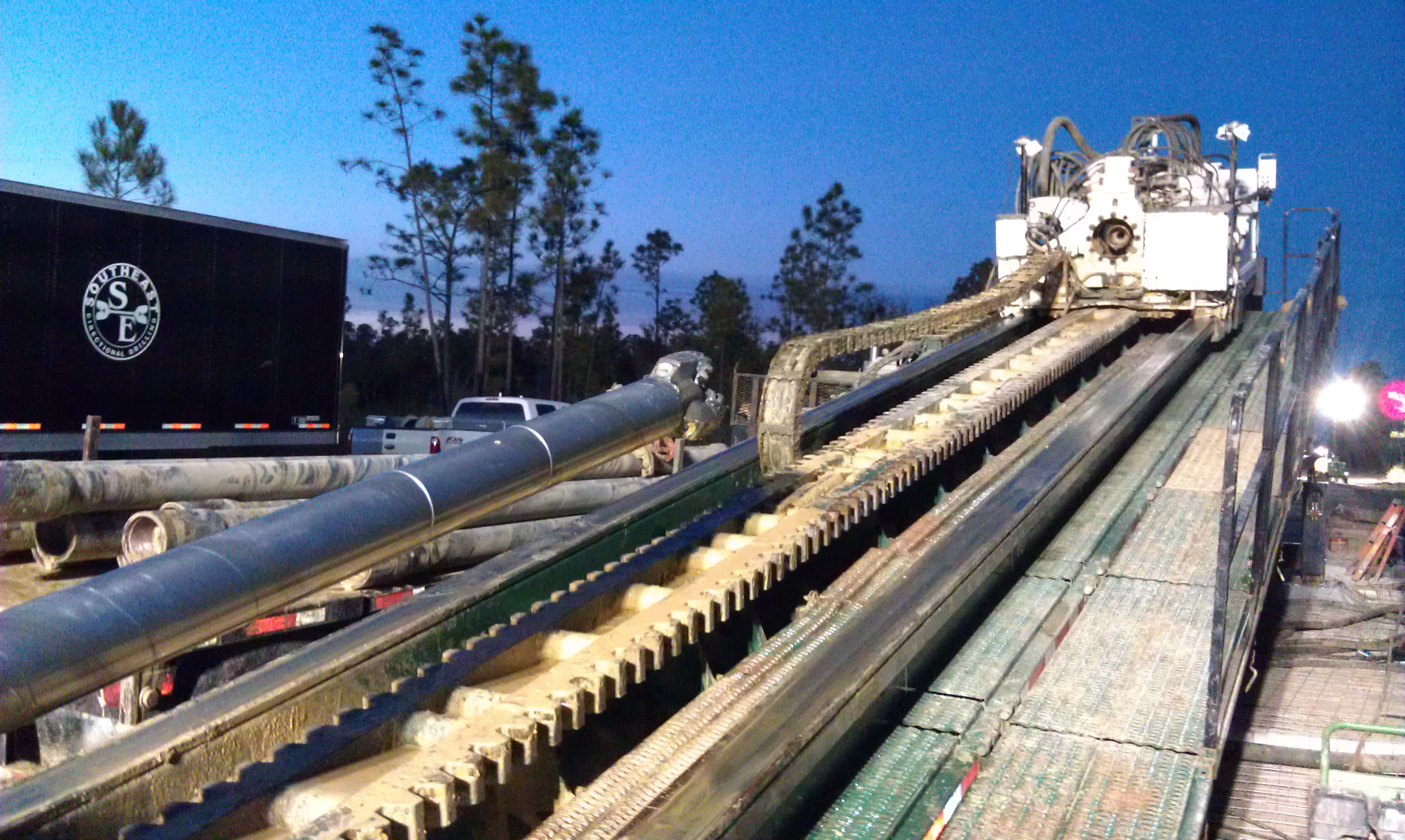
For the bay crossing, Southeast Directional Drilling (SEDD) mobilized two HDD rig spreads. Both drill rigs were modified American Augers machines with pullback capacities exceeding 500,000 pounds, said Mel Olson, vice president of SEDD. Each rig spread included mud systems, mud pumps, drill pipe tooling, and other support equipment.
Further, the bay crossing was not a typical HDD installation.
“We installed approximately 220 feet of 60-inch conductor casing under the Florida Avenue substation at the south end of the crossing to protect the active substation from impacts of the HDD process,” said Olson. “The conductor barrel casing installed by pneumatic hammer was sized so that its 220-foot length would extend through the limits of the substation and its 60-inch diameter size would allow the largest downhole tool — a 48 inch reamer — to pass through. The conductor casing remained in place after completion of the HDD segment.”
After driving the casing to the desired length of approximately 220 feet, it was augered out with 42-inch diameter auger segments connected directly to the rig’s drill stem. Once the final soil material was removed from the conductor casing, a 16-inch diameter centralizer pipe was installed to center the drill stem while completing the pilot hole and ream passes.
Simultaneous drill
After the conductor casing was installed, the substation would not need to be de-energized for the duration of the directional drilling, including the installation of the 36-inch steel casing and HDPE conduit bundle installation.
“The two drilling rigs began drilling simultaneously from opposite ends of the long crossing until they reached the point of intersection near the center approximately 3,100 feet away from each rig,” explained Olson. “Next, the secondary rig retracted drill pipe while the primary rig’s drill pipe followed it up the borehole without deviation from the planned path. During this phase, special tracking software is required in conjunction with the hole intersect method.”
Throughout the drilling process, SEDD monitored operations, including drill times, pull and push pressures, rotary torque, rpm, differential, soils removed, drilling fluid pressures and other fluid data, and gallons per minute being pumped. Disposal of drill cuttings, spoils and displaced drilling fluid complied with applicable regulations, permits and other project requirements.
SEDD completed the reaming operation in two ream passes — a 36-inch diameter ream pass, followed by a 48-inch ream pass. The reaming strategy was subject to change depending on the types of soil encountered when drilling the pilot hole and earlier ream pass. The 48-inch ream pass was followed by a mud or swab pass immediately prior to pulling in the 36-inch steel casing. The drill stem was connected to the pulling assembly consisting of a tapered ball reamer, swivel, shackle and pulling head. Once started, the pullback operation was a continuous operation until completion.

“Pullback installation of the 36-inch steel casing was successful, albeit longer in duration than anticipated,” said Olson. “We had estimated about 20 continuous hours to install the casing as compared to the 68 continuous hours it actually required. The challenges faced were apparent after the initial pullback attempt.”
Challenging geology
The geological formation constantly allowed the drill stem to become key-seated in the bottom of the borehole, creating a challenge to keep the reamer, which is located directly in front of the pulling assembly, from rotating freely as required.
“In order to overcome these challenges during the pullback,” Olson continued, “SEDD delayed pumping ballast water during the initial stages of the pullback in an effort to use the buoyancy forces on the 36-inch steel casing to assist with the rotation of the reamer. We also used a pneumatic hammer located at the north end of the pipeline to assist in breaking the frictional forces throughout the pullback.”
Fabrication of steel casing and HDPE conduits that would go in the casing were performed concurrently with drilling operations.
The HDPE fusion and lay-down area was along right-of-way and adjacent to the 36-inch steel pipe fabrication area.
“HDPE fusion occurred in one location with the conduits extended in length until complete,” Olson said. “Each HDPE conduit was initially pulled along rollers until the fusion process was complete. Once all conduits had been fused to the overall length, the conduits were removed from the rollers and placed on the ground for the preliminary hydro test. Once the test was performed with successful results, the water from each conduit was purged by propelling a foam pig through each conduit with air pressure.”
Once all conduits were dry, they were placed back onto the rollers and bundled for pulling into the 36-inch steel casing. Bundling of the conduits with 2-inch wide, 0.44-inch thick stainless steel banding spaced at eight foot intervals was applied while the pipe was on rollers immediately prior to pullback.
FOR MORE INFO:
Southeast Directional Drilling, (877) 300-2440, www.southeastdrilling.com
Constellation Group LLC, (410) 484 0672; www.cgllc.us
Waldemar S. Nelson & Company, (281) 999-1989, www.wsnelson.com
M&M Pipeline Services/Energy Services South, (662) 258-7101, www.mmpipeline.com
American Augers, (800) 324-4930, www.americanaugers.com
Thermal Grout Key Element In Project
Most power transmission lines are overhead because the heat they generate can cause multiple problems if they are placed underground.
However, advances in cable design and manufacturing, the use of plastics for insulation, and other factors have made underground placement of high-voltage transmission lines a viable option in many situations.
Thermal grout is used to transmit heat from underground electrical cables into the surrounding soil or rock, said Guy Dickes, president, Constellation Group LLC, who over the past five years has been responsible for planning and executing grouting for major underground power transmission projects, including the Wolf Bay underwater crossing.
The right thermal grout mix correctly applied is a critical element in constructing segments of underground power transmission lines.
As grout consultant to the Wolf Bay project, the scope of the Constellation Group’s responsibilities included mix design, technical consulting and operational supervision. The thermal grouting was done after installation and testing of the HDPE conduit bundle. Before the grout was installed, a completed bore path profile was generated and used in developing a strategy for the thermal grout operation in order to fill the extraordinary length and volume of fill specified by design requirements.
“Engineering required thermal grouting to minimize heat build-up as well as physically cementing the bundle of HDPE conduits inside the casing,” said Dickes. “There were four 10-inch conduits for power cables and one 8-inch conduit for fiber optic cable.”
Special mix
In order to achieve pumping distances in excess of one-half mile, the thermal grout needed to be extremely fluid, yet have the necessary thermal characteristics required by Waldemar S. Nelson & Co. engineers. Grout also needed to be homogenous and not separate during the pumping process. The grout had the consistency of latex paint, yet weighed 118 pounds per cubic foot.
Dickes said the grout was manufactured by a local ready-mix supplier, Baldwin Concrete, who dedicated its plant entirely to the project on two non-consecutive days. Specialty admixtures were supplied by Euclid Chemical. Four hundred cubic yards of grout were pumped on one day, 270 cubic yards more two days later.
Drilling contractor Southeast Directional Drilling (SEDD) performed the required thermal grouting in-house and under the supervision of Constellation Group. A Schwing truck-mounted pump was used, and because of the low pressure required, it never was operated above idle speed. The highest pumping pressure recorded was 110 psi, at 20 to 25 cubic yards per hour using several four-inch diameter HDPE grout pipes spaced in the bore. The pumping rate was established to keep pace with the grout delivery schedule and not over stress the HDPE grout pipes. Low pumping pressures indicate easily flowing grout without back pressure.
Mel Olson, SEDD vice president, said the innovative grout mix design resulted in a highly fluid material that was easily pumped and distributed throughout the entire 6,200 feet of casing pipe, effectively interacting with the transmission line while satisfying specified compressive strength of the HDPE bundle contained inside the casing and thermal resistivity parameters for the cable.
“This was the engineers’ first use of thermal grout, and they took a conservative approach to their design,” explained Dickes. “It worked so well, the firm said it would consider utilizing the expanded capabilities for reducing thermal loads in the future. In addition, the Orange Beach cables may be uprated as a result of the better-than-designed thermal resistivity (TR).”

Comments