
October 2013, Vol. 68 No. 10
Features
CIGMAT Report 2013
The main focus of the Center for Innovative Grouting Materials and Technology (CIGMAT) research is on infrastructure maintenances and developing new smart materials for construction, maintenance and repair applications.
The CIGMAT Research Center is currently working on projects related to developing and characterizing smart cement and smart drilling mud for oil well construction and cementing applications; ultra deep water pipe-soil interaction; joint leak testing of polypropylene storm water pipes; and nanotechnology.
In recent years, CIGMAT researchers have developed unique testing facilities including high pressure and high temperature (HPHT) testing of materials and pipelines for oil and gas infrastructure applications and developed test protocols approved by the Environmental Protection Agency (EPA) to test grouts, coatings and pipe joints for infrastructure rehabilitation. A Life Cycle Cost model (CIGMAT-LCC) for wastewater systems have been developed and posted on the CIGMAT website for public use.
In the past two decades, over 60 commercial products including coatings, grouts, liners, cementitious concretes, polymer composites and pipes have been researched and tested for number of applications. The observed trends are analytically and numerically modeled to better understand the influence of various testing and environmental parameters. Every effort is being made by CIGMAT researchers to transfer technology from control studies to actual applications. The industrial members and federal/state/local agencies fund the ongoing research studies at CIGMAT. The director of CIGMAT is Dr. C. Vipulanandan (Vipu), P.E., professor of civil engineering at the University of Houston, Houston, TX.
A year ago, CIGMAT received a research grant of $2.6 million, a three-year grant from the U.S. Department of Energy (DOE) through the non-profit Research Partnership to Secure Energy for America, (RPSEA), to conduct research on developing smart cement and drilling mud for real-time monitoring of oil well installation and performance during the entire service life. Oil Field services firm Baker Hughes is providing additional funding of $500,000 as a cost share. Ongoing researches at CIGMAT are being funded by federal, state and local agencies and industries.
CIGMAT organizes an annual conference and exhibit on the first Friday in March on “Infrastructures, Energy, Geotechnical, Flooding and Sustainability Issues Related to Houston & Other Major Cities” at which speakers are invited from major cities, transportation authorities and energy industries around the country to present and discuss projects and problems related to construction, maintenance and rehabilitation issues. Speakers also discuss technical issues related to maintenance and rehabilitation of water and wastewater systems, nondestructive testing methods, oil wells and pipelines, hydraulic fracturing and development of smart materials for various applications. Geotechnical topics related to expansive clay, rapid deep foundation construction and ground faulting are also discussed. Conference proceedings for the past 16 years are posted on the CIGMAT website at cigmat.cive.uh.edu. The CIGMAT-2014 Conference and Exhibition will be held on March 7, 2014. For conference details, visit cigmat.cive.uh.edu.
Smart cement, smart drilling dud for oil well applications
As deepwater exploration and production of oil and gas expands around the world, there are unique challenges in well construction beginning at the seafloor. For a successful well construction, drilling and cementing operations are critical. During the drilling process it is critical to monitor the changes in the drilling mud due to contamination from formation, fluid loss and circulation loss. During cementing, the flow of cement slurry between the casing and formation, the depth of circulation loss and fluid loss, the setting of cement in place and how the cement performs after hardening needs to be monitored. Recent case studies on cementing failures have clearly identified some of these issues that resulted in various types of delays in the cementing operations. At present there is no technology available to monitor the cementing operation in real-time from the time of placement through the entire service life of the borehole. Also there is no reliable method to determine the length of the competent cement supporting the casing.
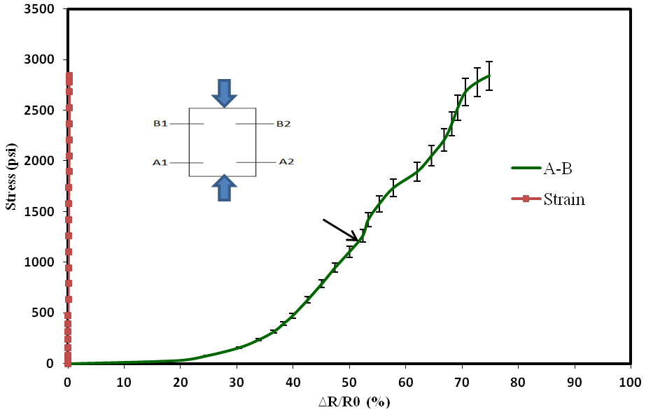
In this study, oil well cement was modified to have better sensing properties, or smart cement, so that the behavior can be monitored at various stages of construction and as well as during the entire service life of the oil wells. A series of experiments were performed to evaluate the behavior of oil well cements both with and without modifications to identify the most reliable sensing properties that can also be relatively easily monitored. For the cement, tests were performed from the time of mixing to hardened state behavior. During the initial setting of the cement, the electrical resistivity changed with time based on the type and amount of additives used in the cement. During the curing of the cement, initial resistivity reduced by about 10% to reach a minimum resistance and maximum change in resistance within the first 24 hours of curing varied from 50% to 300% based on the type of additive. Based on the current study, a new quantification concept has been developed to characterize the curing of the cement based on the changes in the electrical resistivity in the first 24 hours of curing. When the cement was modified with less than 0.1% of conductive additives, the piezoresistive behavior of the hardened smart cement was substantially improved without affecting the rheological properties and setting properties of the cement. For the modified smart cement, the resistivity change at peak stress was about 400 times higher than the change in the strain (Fig. 1).
Drilling mud is used for cuttings removal, suspension of cuttings, release of cuttings at seafloor, minimizing formation damage, reducing filtration rate, cooling and the lubrication of the drill bit and drill string, buoyancy support of the drill string and corrosion prevention. Drilling mud consists of two phases – a liquid phase (water or oil) which is the base and the solid phase which is the clay and other additives. Based on the composition, drilling muds are characterized as water-based mud (WBM), oil-based muds (OBM) and synthetic-based muds. Researchers at CIGMAT are working with all three types of muds to improve performance and enhance the sensing properties. The additives include organic and inorganic admixtures, nanoparticles and surfactants. The xanthan gum (C35H49O29) was very effective in reducing total fluid loss.
The addition of 0.5% Xanthan gum reduced the total fluid loss from 180 mL to 24 mL, about an 80% reduction. Also studies are focused on disaster issues caused by hurricanes and other events during drilling operations. The effect of salt contamination on the fluid loss (30 minutes) on xanthan gum modified bentonite drilling mud is shown in Fig. 2. With 0.5% salt (sodium chloride, NaCl) contamination the fluid loss increased by over 30%. Addition of 0.5% surfactant reduced the fluid loss of the contaminated drilling mud by over 40%, a method that can be used to remediate the salt contaminated drilling mud.

Figure 2. Filter loss in salt contaminated and surfactant remediated
xanthan gum modified water based drilling mud
Deepwater axial and lateral sliding pipe-soil interaction model study
Oil producing subsea systems consist of floating platforms connected to subsea wells by a network of pipelines. Deepwater pipelines laid on the seabed, partially penetrate into the soil based on the submerged self-weight of the pipelines and strength of the soil. These pipelines, when transporting oil and gas in deepwater, undergo significant changes in temperature and pressure during service life. In addition some of the deepwater oil pipelines are on very soft sea bed and are susceptible to axial and lateral movement (or walking) of pipelines due to cyclic thermal changes and lateral buckling due to thermal expansion under operating conditions. Correctly predicting axial ‘walking’ and controlling lateral buckling is extremely sensitive to the selection of pipe-soil interaction parameters during the safe design of the network of pipelines. However the soil resistance to various types of pipe movement is a significant uncertainty and hence the current practice relies on empirical expression for pipe-soil resistance. Although there are several numerical approaches proposed to model the pipe-soil interaction there is very limited experimental studies and quantification of various important parameters for designing and maintaining network of pipelines.
Several physical models have been designed and constructed at the CIGMAT laboratory to investigate the behavior of pipes on the seabed. In this preliminary study, a series of small model tests were performed using instrumented 1.625 in diameter (40 mm) pipes placed on the soft clay soil (undrained shear strength of 1.4 kPa or 29 psf) to better quantify the axial and lateral soil pipe interactions. The resistance to pipe sliding on the soft soil was monitored using a load cell (Fig. 3). The load cell was calibrated and was accurate to 0.01 pound. The pipe displacement was monitored using a linear variable differential transducer (LVDT). The strains in the pipe will be measured using strain gages. This instrumentation will help to better determine the distribution of the soil resistance along the pipe.
Effect of displacement rate and weight of the pipe (vertical load) were also investigated in this model study. Deepwater pipes are insulated with layers of polymers and the outside layer in contact with the soil is solid plastic. The interaction of loaded pipe with soil berms created as the pipe displaced laterally was also studied and quantified. The variation of the frictional parameter with the type (axial and lateral) and rate of loading and weight of the pipe have been quantified. The test results showed that when the axial rate of loading was increased, the frictional coefficient between the pipe and the soil reduced, and the weight of the pipe had no effect on the frictional coefficient within the range of variables studied. The lateral frictional coefficient was higher than the axial frictional coefficient.

Figure 3. Schematic of the test setup for axial displacement study
Triple and double wall polypropylene water pipe-joint infiltration tests
While numbers of small to large older cities are undertaking repairs and maintenance, several other newer cities are planning on installing wastewater systems. Infiltration due to leaking pipes, manholes, laterals and other components of a wastewater system will add to the problem of overflow and substantially load the treatment facilities. Frequent overflows not only lead to regulatory problems but also increase treatment cost. Leaking systems will result in the erosion of soils through the leaking joints leading to the settlement of the ground surface, formation of sinkholes and damage to surrounding pavements and structures. Literature review indicated that Standard ASTM pipe-joint tests varied with the type and size of pipes.
In order to quantify the infiltration at various types of pipe-joints, a unified testing program was developed to test 30-inch diameter sewer pipe-joint up to a hydrostatic pressure of 7 psi. A testing protocol was developed and approved by a steering committee with representation from the EPA, pipe associations, cities and consulting engineers. The testing protocol outlined the procedures to determine the leakage rates at pipe-joints under shear loading and angular deflection. A testing facility was designed and constructed in the CIGMAT laboratory to perform the pipe joint tests in duplicate.
In this study, two types of polypropylene (PP) pipes (triple wall and double wall) were tested. A total of four 30-inch diameter PP pipe joints were tested. During the straight test (unloaded joint), the joint was subjected to hydrostatic pressure incrementally to a maximum hydrostatic pressure of 7 psi with a total testing time of 30 minutes and there was no water leak in the joints. During the shear test, the joint was subjected to incremental shear loading. The maximum shear forces that were applied to the joints varied from 2,268 pounds to 2,899 pounds. The total shear testing time was 2.5 hours and the joint was subjected to a maximum hydrostatic pressure of 7 psi at every increment of shear load and there was no water leak in the four joints tested.

Figure 4. Angular deflection test on triple wall polypropylene pipe joint
During the angular test, the joint was subjected to angular in steps of 0.5 degrees to a maximum rotation of 2 degrees at the joint. The total testing time was two hours for each pipe joint and the joint was subjected to a maximum hydrostatic pressure of 7 psi and the maximum shear load at the joint varied from 292 to 533 pounds during the angular test. There was no water leak in the four joints tested in this study.
Nanoparticles: bacteria interaction
Nanoparticles are being used in number of applications and new generation materials. Hence the effect of different metallic nanoparticles including iron (Fe), silver (Ag), gold (Au) and titanium (Ti) on the bacterial growth are being studied, related to biomedical field, textile field and as antimicrobial agents. Nanoparticles have anti-bacterial properties by either leading to cell wall breakage or by causing oxidative stresses. Several studies also have shown that nanoparticles can promote the growth of bacteria or have no clear toxicity to bacteria. The overall objective of CIGMAT study was to compare and quantify the effects of Au/Fe and Fe nanoparticles not only on the bacterial growth (Serratia sp.) but also on the production of a biosurfactant. The nanoparticles were prepared using the foam method. The concentrations of the nanoparticles used for the bacterial interaction study were varied from 1 mg/L to 10 g/L. The study included the growth of bacteria and production of a biosurfactant when exposed to the nanoparticles up to eight days. In Fig. 5, interactions of nanoparticles with bacterial (Serratia sp.) are shown. The test results showed that the effect of nanoparticles on the bacterial growth and biosurfactant production varied with nanoparticle type, shape and concentrations. Different exposure times of the bacteria to the nanoparticles had varying effects on the bacterial growth. Biosurfactant production was affected by the type and concentrations of nanoparticles. Based on the trends observed in the tests, analytical models have been developed to predict the bacterial growth and biosurfactant production with varying amount of nanoparticle concentrations.

Figure 5. Micrograph of nanoparticle-bacteria interaction of (a) bacteria only; (b) bacteria- Au/Fe nanoparticles; and (c) bacteria-Fe nanoparticles

Comments