April 2014, Vol. 69 No. 4
Features
Model-Based Deep Line Utility Survey
The Subsurface Utility Engineering (SUE) Group of Binkley & Barfield Inc. (BBI) has established a systematic methodology to manage risk through the Quality Level A through D system (QL-A – test holes, QL-B – designation, QL-C – surface feature survey and QL-D – records information) as prescribed by the American Society of Civil Engineers (ASCE).
This framework has proven very successful in preventing damage to existing utilities throughout the nation. Technological advancements in equipment have led to more accurate horizontal positioning of utilities while the vertical positioning has remained a function of the SUE QL-A Test Hole. What alternatives are there when access or economics renders a SUE QL-A Test Hole unfeasible? BBI faced this dilemma on four projects where subsurface utility lines were excessively deep or access for the vacuum truck was not possible.
BBI is a Houston-based engineering design firm with branch offices in Austin, Dallas and College Station that has been in business more than 43 years. BBI provides multiple discipline design services in transportation, municipal and industrial facilities, wet and dry subsurface utilities, telecommunication, overhead and underground electric and power distribution. They also provide inspection services, SUE and through their subsidiaries Baseline Corporation and Landev Engineers Inc., provide survey and land development services.

In October 2013, BBI was asked by Landev to provide SUE QL-A Test Hole Services to find the horizontal and vertical position of a water line and a gas line in one of their large land development projects. These two lines crossed perpendicular to gas lines and Landev needed to know the depth and separation of the crossing line. Review of the requested project quickly revealed that the gas line would require building a bridge to gain access for the vacuum truck. From an economical perspective, the project wasn’t feasible. In further discussions it was discovered that the data required didn’t need to be the Test Hole accuracy of 2 to 4 cm. BBI proposed use of 3D designating technology to alleviate the access and economic issues while still rendering an accuracy well within the client’s needs.
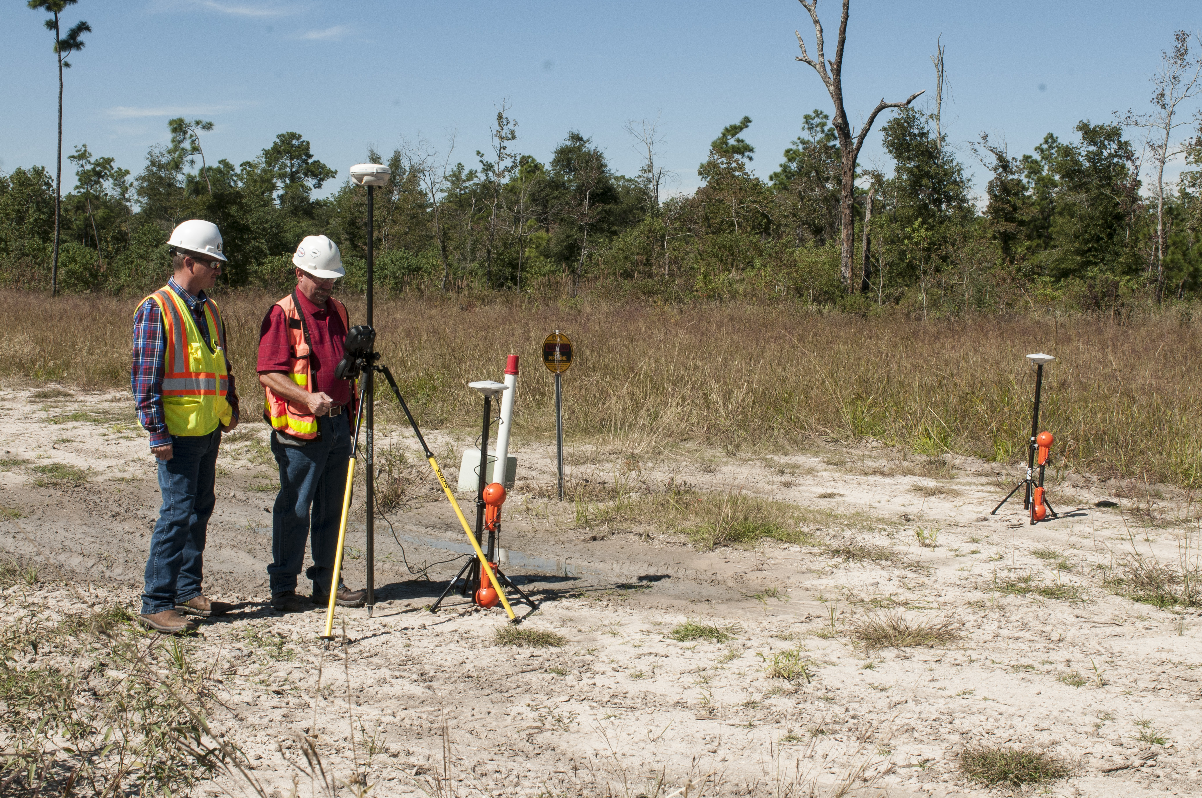
Optimal Ranging Inc. (ORI), Santa Clara, CA, manufactures geospatial utility surveying equipment that provides highly accurate utility location and survey. The equipment is operated using Trimble Access controllers running a Trimble-supplied application called Utility Survey. ORI’s Dual Spar system was selected for its ability to render 3D highly accurate X, Y and Z locations of deep utilities without excavation or line incursion.
Since excavation was not necessary for this SUE QL-B work, BBI was able to immediately go to work without the need to make a call to the area one-call or utility notification center and wait 48 hours. BBI directly connected a low frequency (98 Hz), high output transmitter to the water line test station. The Base and Rover Spar units were then placed perpendicular to the water line, with spacing determined by the anticipated water line depth, using an approximate geometry that would render an equilateral triangle enclosing all three points (Base Spar, Gas Line and Rover Spar). After turning on the Spar units, achieving satellite lock, connection to the Trimble VRS System on the Trimble TSC3 Data Collector, the water line and its orientation appeared on the screen along with the signal strength and confidence level of the data. Geospatial data collection of ground level, offset location, utility location and utility depth were done by simply pushing a button.

To get a smooth profile of the water line, data was collected at eight to 10-foot intervals. After recording all this data, the transmitter was removed from the test station and reconnected to another test station on the other side of the area to be designated (designating from two directions). This entire procedure was repeated on the gas line that was inaccessible to a vacuum truck.
The data collection work on the two lines was completed in less than four hours and did not require any surface restoration or probing. The resulting horizontal and vertical positioning from the data matched the utility location information and was delivered much faster and at a much lower cost than QL-A Test Hole excavation.
The successful use of the Dual Spar equipment prompted use on a gas line in the Monte Belvieu area of Texas. This line was reported to be 35-feet deep and efforts to designate it had been ongoing for over a month. At high cost, twelve, 36-inch diameter by 35-foot deep test holes had been excavated in the attempt to locate this line. Using the Dual Spar methodology, the gas line was designated in less than two hours and shown to be at a depth of 33.5 ±1.2 feet. The line was immediately excavated via hydro excavation at the new location and found. The depth of the line was surveyed at 34.1 feet (an eight-inch difference between the exposed depth and the remote sensing depth and within the reported error).
That same day, BBI went to another gas line location and used the Dual Spar to locate two lines crossing under Beltway 8. These lines had proven to be un-locatable by standard methods due to interference from electric towers. Both of these lines will be crossed by a directional bore. Knowing the horizontal and vertical locations of these lines to complete the design of the directional bore is critical.
Again the Dual Spar System quickly collected the X, Y and Z data on the two lines and work was completed within four hours. The collected data showed the gas line depths to be 16.1 (±0.9) and 15.4 (±0.8) feet deep at the crossing of the directional bore. The utility owners requested a QL-A Test Hole on each gas line at the crossing of the directional bore. The test holes were excavated at the locations the Dual Spar indicated and the depths were 16.8 and 15.8-feet deep (nine- and five-inches difference and within the confidence intervals reported by the software).
A short time later the utility provider requested another SUE QL-B Designation using the Dual Spar on a gas line running diagonally under Beltway 8. Improvements to an overpass required new piers going as deep as 60 feet and the diagonal running gas line threads the needle between them. The gas line was reported to be 48-feet deep and there had been numerous unsuccessful designation attempts over a period of a year. A 60-inch diameter by 50-foot deep test hole was also unsuccessful in finding the gas line. A smart pig had been used to give an approximate location of the gas line and showed the proposed pier locations to be within eight feet. The utility provider wanted additional verification of the gas line location and due to the depth, there wasn’t adequate time to perform another test hole excavation.
During field investigations, BBI found substantial utilities at varying depths, crossing and running parallel to the gas line. Direct connection via a test station was successful and the transmitted signal could be picked up through an area of interest but stopped at an electric tower. Direct connection to a test station on the other side of the project was successful but the signal again stopped at the same electric tower (which was now between the test station and the area of interest). Unlike the other projects, this forced the use of a single direction in performing the designation.

During data collection, it was noted that the Dual Spar was showing that many locations did not have a good confidence level due to presence of other utilities in the same right-of-way. This required an adjustment to the locations of both the Base and Rover Spars, and the separation between spars. Other challenges involved the existing highway overpass shadowing the GNSS satellite signals from the Spar units, which require GPS time synchronization in Dual-Spar mode. This was quickly solved by placing “Spar points” with a total robotic station and pole mounted prism and entering them into the Trimble TSC3 Data Collector. All the collected data was processed to render an output in the coordinate system used by the overpass designers and the smart pig. The resulting line very closely followed the smart pig and showed that the 50-foot test hole had only missed exposing the gas line by a few feet. From mobilization to the site, collection of and processing data and issuing a report was three working days.
Remote sensing has always been seen as the safest, lowest cost, and most convenient way to find utilities. Unfortunately reliable elevation data is not attainable with conventional tools. The Dual Spar reports geospatial elevations of the targeted utility, and renders vertical accuracy which has not been previously realized by existing electromagnetic locating equipment. Should this be considered a replacement for performing test holes, which can cost thousands of dollars (or much more, depending on depth)? Where some variation in the location is acceptable, the answer is yes. For those occasions where absolute location is necessary, the answer is perhaps not.
At a minimum, the reported horizontal and vertical accuracy of a Dual-Spar measurement can help determine where test holes are required. There will always be times where nothing but exposing a utility will satisfy the project requirements so test hole utility elevation determination will remain a key component of SUE. But in situations similar to those presented here, Dual Spar underground utility positioning technology represents a more economical alternative when managing SUE costs and risk.
SIDEBAR:
Conventional locating methods depend on searching for peaks or nulls in the electromagnetic field, manually marking those locations and surveying the markings separately. This is an inefficient process and may lead to ambiguous or erroneous results, particularly for deep utility lines when detecting the precise location of the peak signal is difficult. Using ORI’s model-based technology, the utility can be accurately positioned without being directly above it or at any other special location. Vegetation, water or other obstructions over the utility path do not interfere with accurate positioning of the utility.

Dual-Spars are better able to characterize the expected circular model of the magnetic field arising from a current applied to deep directionally bore lines. The method uses simultaneous field measurements from both spars and is a generalization of the simple ratio measurement that handheld locating tools make at the peak signal (top of the circle). An advantage of the new approach is that the accuracy of the estimates (statistical confidence) is computed based on the non-circularity of the measured field. Systems that rely on a simply ratio measurement cannot provide error estimates with the 3D position and therefore have been utilized primarily as 2D location tools.
FOR MORE INFORMATION:
Binkley & Barfield, (713) 869-3433, http://binkleybarfield.com
Optimal Ranging, (408) 715-1222, http://www.optimalranging.com
Comments