August 2014, Vol. 69, No. 8
Features
Solving Stray Current Mitigation In Portland’s Rail System
From the modest beginnings of horse-drawn rail cars on First Avenue in the early 1870s, light rail in Portland, OR, has flourished, declined and gone through a resurgence.
By 2030, planners forecast a million new residents in the Portland metropolitan area. The Portland-Milwaukie Light Rail project is a key component in the planning effort connecting Clackamas County, one of the region’s fastest-growing areas, with Portland State University (PSU), the number one destination in its transit system. Light rail systems such as this impose unique impacts to utilities within the light rail corridor. This fast-tracked project mitigates those impacts while reducing construction duration and cost and minimizing the impacts to businesses along the alignment.
The South Corridor Project –led by Metro in partnership with Tri-County Metropolitan Transportation District of Oregon (TriMet), the city of Portland, the city of Milwaukie and Clackamas County – has worked to identify transportation options for the fast-growing Interstate 205 (I-205) and Milwaukie/Oregon city corridors. When the study began in 1999, light rail was not an option under consideration. But neighborhoods along the alignment – from Southeast Portland to Milwaukie – requested that light rail be part of the study and it was ultimately adopted as the preferred option.
Subsequently, the South Corridor Project has followed a two-phased approach. In September 2009, Phase 1 brought Metropolitan Area Express (MAX) Green Line service to the I-205 corridor between Clackamas Town Center and Gateway, where it then uses the existing MAX Blue and Red line tracks to travel to downtown Portland. Once the Green Line crosses the Steel Bridge, it follows new tracks along the Portland Mall to Portland State University. Portland-Milwaukie light rail constitutes Phase 2 of the South Corridor Project, with Phase 1 being Portland Mall light rail.
History
In the 1870’s, Portland’s first trolleys were horse- and mule-drawn, operating on First Avenue from NW Glisan Street to SW Caruthers Street. As the 1900s came, the Portland metropolitan area had the first interurban electric rail service in the nation. By 1912, Portland saw its high point of 28 electric rail lines, when the population of the city was 250,000. However, after World War I, electric rail lines began to feel the pinch from the emergence of the automobile. During the Depression in the 1930s, streetcars began being replaced with buses and in 1950, the last street car was retired.
By the 1960s and 1970s, Portland was violating federal clean-air standards on a consistent basis. Concurrently, a controversial new freeway, the Mt. Hood Freeway, was in the planning stages. This freeway would have sliced through Southeast Portland, forcing thousands to relocate. Grass-roots efforts around the city called attention to the general distaste for new freeways and affected local elections. These efforts resulted in the election of anti-freeway politicians to city and county offices, and these new administrations successfully lobbied and abandoned the Mt. Hood Freeway plan.
TriMet was established in 1969 after the previous transit provider, Rose City Transit, was not doing enough to generate ridership while meeting federal air quality standards and went bankrupt. TriMet quickly absorbed many of the outlaying suburban bus services over the next few years. TriMet also began preparing for rapid transit solutions, opening the Portland Transit Mall to buses in 1975 and studying light rail. After the decision was made to kill the Mt. Hood Freeway in the 1970’s, light rail in Portland went to the forefront of plans to improve the traffic problems in the Portland Metro Area. Momentum increased when legislation was passed in the U.S. Congress to allow funds from abandoned freeway projects to be used for urban transit projects. Residents voted in favor of constructing what was then called the Banfield Light Rail Project, named for the freeway (I-84) which the majority of the alignment followed.
In September 1986, the Eastside MAX line opened for revenue service, spanning 15 miles from Gresham to downtown Portland. One of the first light rail systems in America, Eastside MAX helped set the standard for the future of American light rail design. It also marked a critical point in Portland’s history, as the region went away from automobile-focused urban design to become a civic leader in land use and transportation.
In 1998, the Westside MAX line, TriMet’s first extension of its light rail network, opened for revenue service, spanning 18 miles from the fast-growing high-tech corridor in Hillsboro to downtown Portland. One of the largest public works projects in Oregon’s history, it included twin tunnels, each tunnel being 21 feet in diameter and spanning three miles through Portland’s West Hills area.
Portland International Airport (PDX) had seen steady growth for many decades, becoming America’s fastest growing airport in the late 1990’s. Additional access was needed to address the increase in traffic congestion at and around the airport. The Airport MAX line, the first “train to plane” connection on the west coast, was also the first to take passengers directly to an airport terminal.
In April 2004, four months ahead of schedule and $25 million under budget, the Interstate MAX line opened for revenue service. Fred Hansen, TriMet’s General Manager at the time, referred to this line as the “phoenix line,” rising from the ashes of a previous and more extensive light rail project. In 1998, voters defeated a ballot for a north-south light rail from the southern-most portion of Portland to North Portland. However, a majority of the residents in North Portland voted in favor of the line, as this area was long in need of revitalization and would benefit substantially from the presence of light rail. With the community’s backing, TriMet decided to construct the Interstate MAX line, extending 5.8 miles from Portland’s Rose Garden Arena to the Expo Center.
Portland Mall Light Rail (Green Line)
When the Portland Mall was completed in 1978, it instantly received international attention as a model for transit and downtown redevelopment. What the Portland Mall revealed was a prototype for the redevelopment of a downtown, using a transit project as the catalyst. Today the Portland Mall – commonly referred to as the Transit Mall – serves many purposes. It is the front door for office buildings and retail businesses. It is a transit facility with the highest concentration of bus service in the city. It is an important public space comprising 17 total blocks in downtown. However, after more than 25 years of service, time had taken its toll. The most noticeable problem was that it looked worn out. The bricks and granite pavers were cracked in many places and the benches and other furnishings needed repair or replacement. Several businesses found that the Mall had been a poor front door for their businesses. Some even closed entrances that front Fifth and Sixth Avenues.
The city of Portland joined with TriMet to undertake the Portland Mall Revitalization Project. Portland Mall Light Rail was a key element in the planning effort connecting Clackamas County, one of the area’s fastest-growing areas, with Portland State University (PSU), the primary destination in TriMet’s transit system. With a million new residents projected in the region, this extension of the region’s light rail system was considered to be a key element in the long-range regional transportation plan. This extension positioned the region for future growth of high-capacity light rail to the southeast and southwest portions of the metro area.
In September 2009, construction of the 8.3-mile alignment was complete, bringing the region’s total light rail system to over 52 miles and allowing light rail riders to make connections between Clackamas County and Gresham, PDX, Washington County, North Portland and downtown Portland.
The Portland-Milwaukie Light Rail Transit Project will create a light rail alignment that travels 7.3 miles, connecting Portland State University in downtown Portland, inner Southeast Portland, Milwaukie and north Clackamas County (see Figure 1). MAX service on the alignment is scheduled to begin in 2015. By 2030, this light rail line will carry up to an average of 22,765 to 25,500 weekday rides, and there will be approximately 22,000 households and 85,000 employees within walking distance of Portland-Milwaukie light rail stations.
Impacts to utilities
Light Rail Transit (LRT) system operations impose two unique impacts to utilities within the LRT corridor. The first and most obvious impact is that, unlike cars or buses, light rail trains cannot be detoured around obstructions in the road when, for instance, a water line breaks. Utilities which lie underneath the tracks must be either relocated or improved to minimize the possibility of breaks and mitigate the need to tear up the road and shut down LRT operations during routine or emergency utility maintenance.
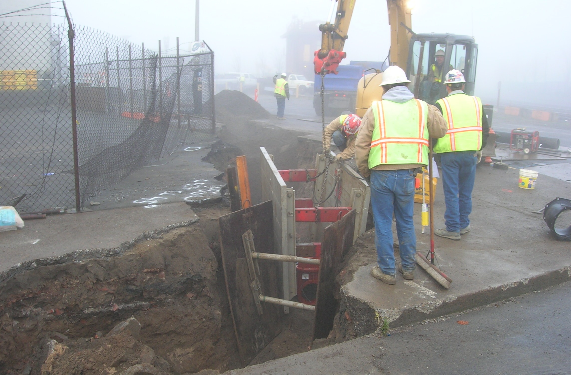
Due to safety constraints, construction crews are restricted from working too closely to moving trains or the high-voltage catenary power lines installed overhead. Further, excavation beneath or bordering the track is restricted due to the potential of undermining the track as well as reducing the load on the existing utility. Construction parallel with rail systems can be more challenging than crossing under the track, because these excavations warrant trench safety systems such as shoring to support the trench and protect crews. In streets that are congested with other utilities, such as downtown Portland, shoring can prove to be a challenging task in itself (see Figure 2). An additional challenge with excavations parallel to rail systems is the physical limitations of the heavy machinery used to install and maintain utilities. Construction machinery generally spans the excavation, which may infringe upon the rail system right-of-way and impede train movement.

Bonding wires installed across each pipe joint creates a continuous electric circuit between corrosion test stations. (photo courtesy of Portland Water Bureau)
The second, and less obvious, impact of a new light rail system is stray current corrosion. Light rail trains are powered by electricity. Electrical current travels in a circuit from the power station to the train via the overhead wires above the tracks through the train’s electric engine and back to the power station via the rail and ground. Because the soil serves as a parallel conductor to the track, a portion of the current will return to the power station through the ground. The current returning through the ground is known as a “stray current,” due to the fact that it follows a path other than that intended. Electric current in the ground will use the most conductive medium to return to the power station. Iron and steel water pipes are often good conductors. However, when the current leaves the pipe, it takes electrons with it and corrodes the pipe.
The basic fundamental cause of corrosion can be explained in terms of energy. It is much more natural for a metal to exist in the form of a compound, since compounds such as oxides contain less energy than metals and are therefore much more stable. When metallic pipes are made, iron is separated from its associated oxygen in a blast furnace. This produces a lot of energy in the form of heat. As long as they remain metallic, steel and iron pipes retain this energy, bound up within itself, with a natural tendency to corrode back to the ore from which it was derived. It is this energy that drives the corrosion process.
In order for corrosion to occur, there must be a complete electrical circuit, including an anode and a cathode. The anode is the location where the current leaves the metal, and the cathode is the location that the current flows to. In the case of electric light rail systems, the current goes out from the substation along the overhead wire until it reaches the train, passing through the motors and theoretically returning along the rails to the substation. However, if a reasonably low-resistance parallel path exists, whereby the current may follow pipelines and cables to return to the negative ground of the substation, a portion of the current will take this route. In these cases, the current follows a parallel metallic path, such as a water main. Portions of water mains can be electrically continuous due to typical construction methods such as leaded joints on cast iron pipes and mechanically restrained joints on ductile iron pipes.
Where the current jumps from the rails to the water main, the rail is serving as the anode and the water main is serving as the cathode. In these cases, the water main is protected, because electrons are not being removed from the pipe. Where the current leaves the water main to enter the lead cable, the water main is serving as the anode and the cable is serving as the cathode. In these cases, electrons are leaving the pipe with the current and the pipe is corroding. Table 1 presents a galvanic series of selected metals common in construction. In a galvanic cell of two dissimilar metals, the more active metal will act as the anode and be corroded. The more noble metal will act as the cathode and be protected.
Galvanic Series of Selected Metals Common in Construction
Anodic, Active (Read down)
Magnesium
Zinc
Aluminum
Mild Steel
Wrought Iron
Gray Iron and Ductile Iron
Lead
Tin
Brass
Copper
Stainless Steel, Type 304
Stainless Steel, Type 316
Titanium
Silver
Gold
Platinum (Read up)
Cathodic, Noble
Corrosion Solution
In the complexity of a metropolitan district, the path of stray currents can be difficult to follow. To reiterate the important point, anodes corrode; cathodes do not. As such, it is only necessary to make a pipeline sufficiently cathodic to prevent its corrosion. If a current is passed from the earth to a pipeline, the incoming currents will nullify any outgoing currents from the anodes of local corrosion cells. Further, the pipe, receiving current over its entire area, will be immune from corrosion. A current through the earth can be easily produced by galvanic action from the energy of corrosion of a magnesium anode. In this case, a piece of magnesium is connected to the pipe with wire and buried, away from the pipe. Because magnesium is much more active than the iron or steel in the pipe (as demonstrated in Table 1), a considerable voltage is established between the magnesium and the pipe. Current will flow from the magnesium (anode), through the earth, to the pipe (cathode). The electrical circuit is completed when the current flows from the pipe to the anode through the wire (see Figure 3).
Today, the vast majority of buried pipelines are coated with some kind of organic coating. Corrosion can be prevented completely by either maintaining a perfect coating or impressing a protective cathodic current density on a bare line. Maintaining a perfect coating is impossible as a perfect coating does not exist. Impressing a protective cathodic current density is overly expensive due to the high current demand. Somewhere between these two extremes lies the economically optimal combination of a good coating supplemented by cathodic protection to protect the inevitable imperfections in the coating
On previous light rail projects, the city of Portland Water Bureau developed a 10-foot separation criterion between the track and water mains, which combined the requirements for access, corrosion control and cost/benefit. With this “Electric Rail Design Criteria” (ERDC), all water mains within 10 feet of the proposed track slab were to be relocated. Further, all mains crossing under the track were to be steel-encased ductile iron (DI) pipe with the casing extending 10 feet from each side of the track slab (see Figure 4). All told, over 8,000 feet of the Bureau’s water mains have been relocated, ranging in size from six to 36 inches.
Existing service lines and hydrant runs crossing under the track slabs have been replaced with PVC-encased DI or copper, depending on the existing pipe size.
To mitigate the impacts from stray electric currents, 30-pound magnesium anodes have been placed every 100 feet along the pipeline. Further, insulating joints, consisting of two flanged pipe ends with a di-electric gasket in between, have been placed at connections to existing mains, as well as at each end of the steel-encased mains. These insulating joints prevent stray currents from traveling too far along the pipeline. Test stations are located at these locations to monitor corrosion. A continuous electric circuit will be created between corrosion test stations by installing bonding wires across each pipe joint (see Figure 5). As an additional measure, all ductile iron pipe will be wrapped with 4-mil polyethylene encasement (see Figure 6).
Transmission main improvements
The Bureau maintains several large diameter transmission mains that convey water from the city’s main supply in the east into downtown Portland. Two of these, an existing 30-inch cast iron pipe in SE Division Place and an existing 36-inch ductile iron pipe in SE Caruthers Street, were replaced and installed in 48-inch and 54-inch steel casings, respectively (see Figure 7).
In addition, the new light rail tracks will cross the Bureau’s Washington County Supply Line (WCSL). This 60-inch pipe delivers up to 60 million gallons of water per day from Powell Butte to wholesale customers in the Tualatin Valley and Raleigh Water Districts and the city of Tualatin. Options for maintaining this water supply included replacing it with a new 60-inch steel pipe or protecting the existing concrete pipe in place. In the end, it was decided to protect it in place with a concrete box culvert (see Figure 8), as new steel pipe that size could not be supplied and installed during the off-season window of time that the WCSL could be taken off-line.
Maintaining business and pedestrian access was critical to the success of the project. TriMet has been working closely with its contractors to speed the pace of construction and ensure that customers always have access to businesses. Crews worked in three to 5-block work zones for up to eight weeks, and then moving to the next work zone, ensuring that construction impacts were minimized.
This innovative engineering project provides a water system that will not impact LRT operations during routine or emergency utility maintenance. Further, the project provides cathodic protection from stray electric currents common with LRT projects. Measures were taken to reduce the construction duration and cost while minimizing the impacts to downtown businesses and their respective customers.
FOR MORE INFO:
Kennedy/Jenks Consultants, (503) 423 4016, www.kennedyjenks.com
Comments