
March 2019 Vol. 74 No. 3
Features
First Look: Utilizing Inertial Navigation Technology for 3D Mapping, Locating, Management
First Look
Over the last two decades, significant advances have been made in the quality and application of inertial navigation technology targeted at mapping underground pipe and duct assets. This article provides information on pipeline technologies that are available to map a minimum internal diameter (ID) of 1.6-inch to larger sizes. The pipeline mapping system offers a range of solutions that can map any pipe, regardless of its material, depth or type of utility.
Location, location, location…is the primary concern when it comes to underground infrastructure operations, maintenance and rehabilitation. Most pipeline operators are investing heavily in state-of-the-art geographic information systems (GIS) to store network-related data, including XYZ.
However, the quality of XYZ data populated from a GIS platform is often inaccurate or inadequate due to:
- Aging or lacking information
- Unknown depth
- References to no-longer-exising, above-ground landmarks
- Original data is non-digital
- Use of a multitude of scales and coordinate systems, making exchange of data very inefficient
- Inability to map infrastructure installed by means of trenchless methods, such as river cross- ings, underneath buildings,
The risk is, therefore, high that costly GIS platforms become populated with inaccurate and low-value XYZ data, yet the value of a GIS platform is directly related to the quality of the data contained in it.
The main problem is often that there is no accuracy label attached to data stored in GIS platforms and, as a result, the quality of data is reduced to the lowest-common denominator.
Low-accuracy data significantly increases the risk of future damage.
Inertial navigation technology
Traditionally, inertial navigation was developed for the airline, marine and defense industries, but today can be found in applications such as GPS systems and smart phones.
Inertial Navigation Probes typically contain a range of inertial sensors such as gyroscopes, accelerometers and magnetometers. The object of an inertial navigation probe is to frequently measure the angular rate of change of its core axis; i.e. changes in heading (azimuth), pitch (inclination) and roll. Distance is measured to give length to the resulting vector angles so that a three-dimensional profile can be created.
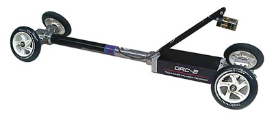
DuctRunner-technology-based probes operate autonomously, as there is no tethered data cable or surface tracing required. As a result, pipes and ducts can be mapped to any depth and may cross any terrain. Measurement accuracy is dependent on several factors.
First and foremost is the quality of the probe and data processing software. Second, the better the probe is aligned inside the pipe, the more accurate the result. Centralizing spacers are recommended to obtain optimal alignment but are not always operationally possible. For example, an aging wastewater pipe tends to have many ill-fitting lateral connections and joints that may hinder the centralizers from passing smoothly. In such cases, it is operationally more efficient to run the probe along the invert of the pipe.
A third factor affecting accuracy is the skill of the operational team. Pipeline mapping systems have many built-in algorithms to detect errors and inconsistencies, but it is up to the operators to follow the recommended procedures and assess the logged data. Incorrect conclusions or handling may affect accuracy.
Although operational accuracy cannot be guaranteed, achievable accuracies are in the order of 1 foot/2000 feet in the XY (horizontal plane) and 1 inch/4000 in Z (depth).

Inertial-navigation-based solutions are an accurate and valuable addition to the array of mapping technologies available today.
True, they can only be used when an empty or water-logged pipe or duct is available, but within that segment they are by far the most effective technology.
Most non-gyroscopic mapping systems require personnel to trace the path of a pipeline using either a beacon system or ground-penetrating radar. However, none of these systems get the exact measurement of the pipe’s center-line. Moreover, beacon-based systems can measure to a limited depth and are highly susceptible to electromagnetic interference, rendering them virtually useless in densely piped areas or near railways and power lines.
Verification of GIS Data for Existing HDD jobs
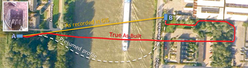
A telecom operator was informed that a canal it crossed with an HDD was about to be dredged to deepen it. To ensure the existing HDD conduit was installed deep enough, the operator requested to map the pipe segment between manholes A and B using pipe mapping tool. The operator knew that the data in the GIS platform (original installation was in 1998) was incorrect (yellow line) because the pipe entered manhole B from the south. The telecom operator presumed the HDD bore had been drilled in a long curve (white dotted line).
After completing the mapping, it turned out that the true as-built (red line) was in a significantly different location than presumed or drawn. Following this measurement, the operator decided to obtain true as-built maps of all HDDs that were recorded in the GIS platform as a straight line between the entry and the exit point. On the upside, the existing drilling turned out to be deep enough.
Assessment of Pipe Bundle Torque
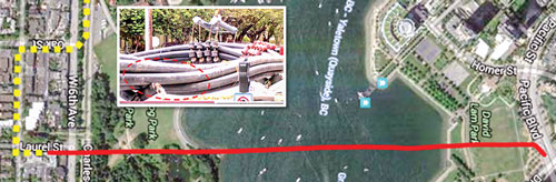
A power utility had a 3,300-foot long HDD cable installed under the False Creek in Vancouver, Canada. Six, 10-inch HDPE conduits of cables were pulled in but could not be aligned with the HDD exit point in Laurel Street, so they were pulled through a series of 90-degree bends (yellow dotted line).
To get through the 90-degree bends, the bundle of ducts had to twist 180 degrees. The client was concerned that as the bundle was pulled into the borehole, the torque effect would continue with the power cables. In that case, a higher drag factor had to be accounted for, thus requiring a stronger and more-expensive power cable.
Reduct mapped four of the six pipes in one afternoon. The resulting profiles were projected in a 3D viewer which showed that the pipes remained almost perfectly aligned and did not torque. As a result, the less-expensive power cable would serve the needs.
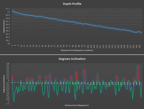
Inclination assessment of a gravity sewer
In post installation of a new gravity sewer, the client required verifi- cation of exact inclination of each segment.
When the pipe was installed, one GPS reading was taken on each joint using a conventional GPS surveying method. However, the client wanted to verify that the pipe had not shifted vertically.
The pipeline mapping system logs at 100Hz (100 samples per second) and the probe was pulled through the pipe at about 3-feet- per-second, giving a point frequency of about 0.5 inches.
Contrary to the conventional method, the result showed several locations where the pipe inclination was positive rather than the specified –0.5 degrees.
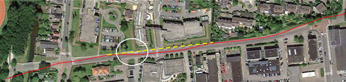
HDD Steering Affected by Electromagnetic Interference
An HDD contractor used a walk-over beacon system to steer a 1,700-foot-long HDD installation in Michigan. The design specified that the drilling followed the northern sidewalk. The figure below highlights (white circle) where the beacon signal was lost, probably due to electromagnetic interference.
But the rig master steered “blind” until the signal was picked up again—about 7 feet away from the planned profile (yellow dotted line). The utility owner insisted on the post-installation measurement to avoid future damage to its infrastructure. It also revealed a sharp change in depth at the same spot.
Operational aspects
Operational efficiency is a key factor for the market to embrace new technologies. Due to its high logging rate (100 Hz), DuctRunner probes can travel up to 6-feet-per-second. For example, a skilled team will be able to complete the mapping of a 2,000-foot long HDD project in just one hour.
Another very important benefit of these mapping systems is that they are insensitive to electromagnetic interference and can therefore be used near power cables, train tracks and other sources of electromagnetic disturbances.
The data output is open-platform based and the user can save data in xlsx, csv, AutoCAD script or xml format in the desired point frequency. This means that measurement results can seamlessly be uploaded to all commonly used GIS platforms.
There are three efficient moments in a pipe’s lifecycle: initial installation, during maintenance or during rehabilitation. Obtaining accurate as-built date directly following initial installation is by far the easiest and, thus, most economical moment. The reason is that the pipe is accessible, segment lengths are reasonable, and the pipe is clean or empty of cables. However, the reality is that accurate as-built requirements, particularly for trenchless installations such as HDD jobs, tunneling, etc., typically lack specifications, so “as-built” is often not more than “as-planned” or “as-wished.”
Independent as-built verification is essential for trenchless installations and pipeline owners/operators should not accept anything less than the best information. Direct and consequential damage to a pipe segment installed by trenchless method is infinitely more expensive to repair than damages to trenched pipes.
Lastly, if, as a utility operator, you wish to have your GIS platform populated by high-quality data 30 years from now, you must start collecting high-quality data today. Take no risk, get it mapped. •
FOR MORE INFORMATION
Otto Ballintijn, otto.ballintijn@reduct.net
Santosh Saride, santoshs@condux.com

Comments